The Arduino Mega power and prototyping shield provides:
- An independent, buffered, LED on every I/O pin
- A 30V 500mA output on every I/O pin
- Two buttons
The Arduino Mega power and prototyping shield provides:
This page covers the Rev 1.0.0 Mega LED & Power Proto Shield. I plan on making 10 total, and have only completed 4 so far. My goal is to made a new revision that addresses some of the problems with the Rev 1.0.0. If you really want to buy one of the Rev 1.0.0 units, I have a couple available (though the pins may have been bent and re-straightened). Email the address at the bottom of the page if you are interested.
Here is the quick start guide for using them.
Before using this, keep in mind that:
As with most Ardunio shields, misuse of the Mega Power & Proto shield may result in damage to your Arduino. Here is a list of the most common issues that you may encounter.
Removing the thing is difficult due to the number of pins connecting the shield to the Arduino Mega. If you simply pull them apart there is a good chance of bending a few of the pins. You can straighten them again with small pliers, but they aren't as nice afterword. When pulling it apart, slowly and carefully work it off. I have had some luck partly unplugging it and then using a nylon pry tool to get it the rest of the way off. But I need to find a better solution.
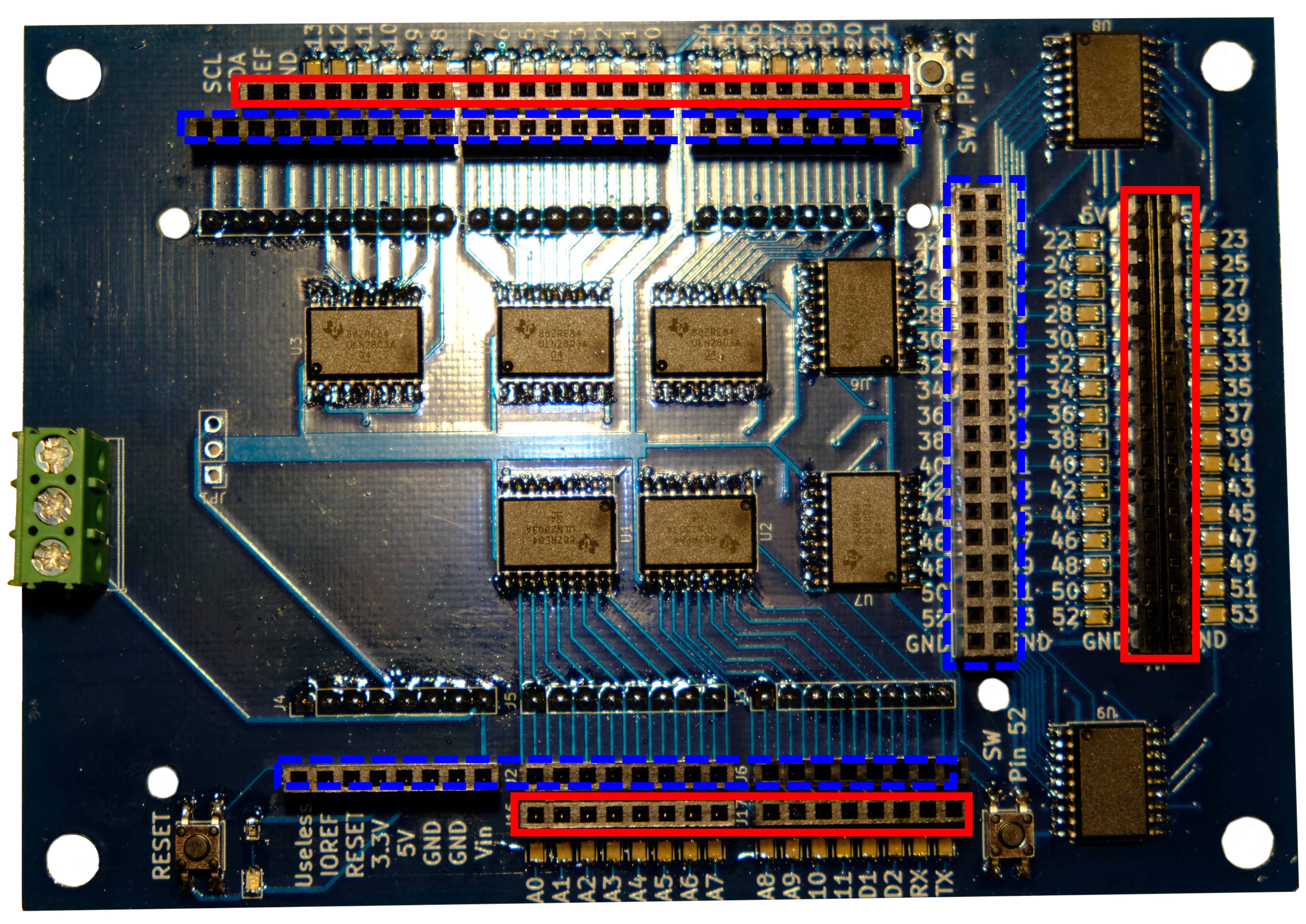
There are two buttons included, one wired to pin 52 and the other to pin 22; the other side of each button is wired to ground. They are normally open, so you can use the pin for something else and simply not press the button. This also means they don't have pull up/down resistors. When using them you should enable the pull up resistors using INPUT_PULLUP:
pinMode(22, INPUT_PULLUP);
The buttons are not debounced. If necessary, you could use a software debouncing approach. For many Arduino projects the bounce is not a problem.
A reset button is also included since the on-board reset is covered up. Resetting your system by pounding on it with a hammer is not recommended.
Each Arduino I/O pin is connected to a Darlington transistor inside a ULN2803A transistor array, as shown in the schematic. When an Arduino I/O pin is high the Darlington transistor connects U3 to ground, allowing current to flow both through the on-board LED and through any attached load. When the I/O is low the Darlington transistor appears as a high impedance and current does not flow. As this may result in a high voltage at U3 there is a protection diode in series with the LED, preventing the high voltage from feeding back into Vcc.
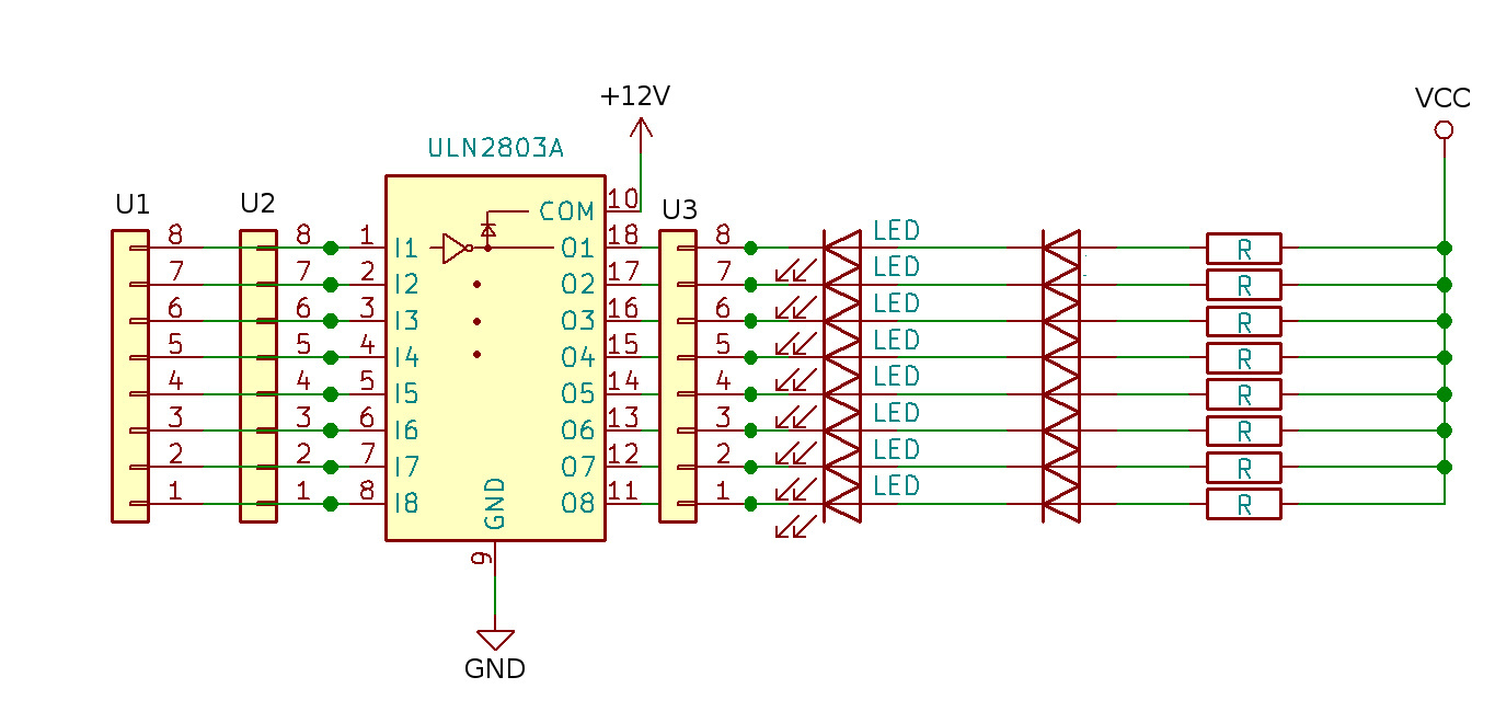
Figure 1: This wiring scheme is used on all I/O pins.
Each array of Darlington transistors should be limited to 2.4 amps total, as imposed by the trace connecting each ULN2803A to ground. The entire system should be limited to 18 amps, which is the current limit on the screw terminal.
Advanced users should review the TI ULN2803A datasheet for details on the Darlington transistor arrays used in this design.
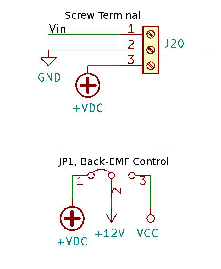
The screw terminal allows easy connection for the higher voltage you plan on controlling, as well as external power for the Arduino. While it could be any voltage up to 30V, I call it +12V for convenience. The ULN2803As will handle up to 50V, but I don't recommend working with voltages that high on this board. Strictly speaking, it is not necessary to wires up the +12V; you only need the shared ground. Wiring up +12V allows for connecting the back EMF suppression diodes and also provides a convenient place to wire up your high power device.
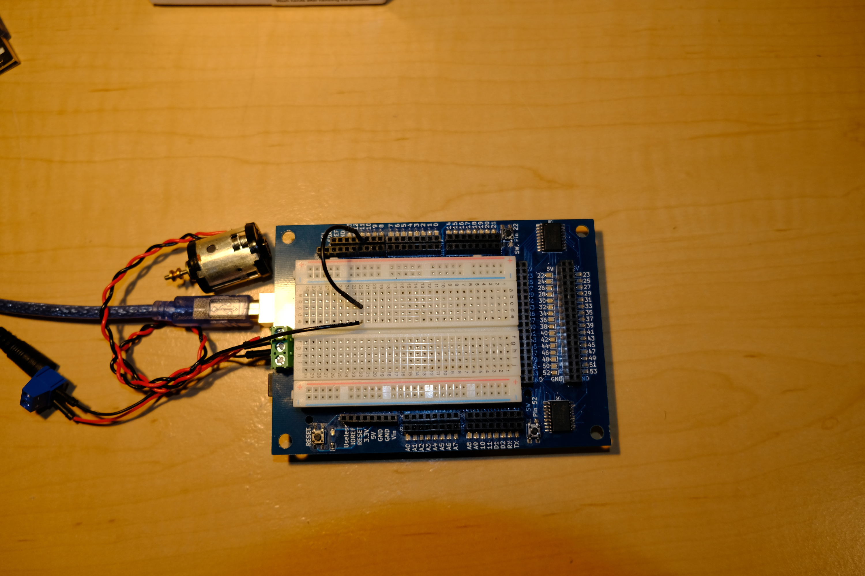
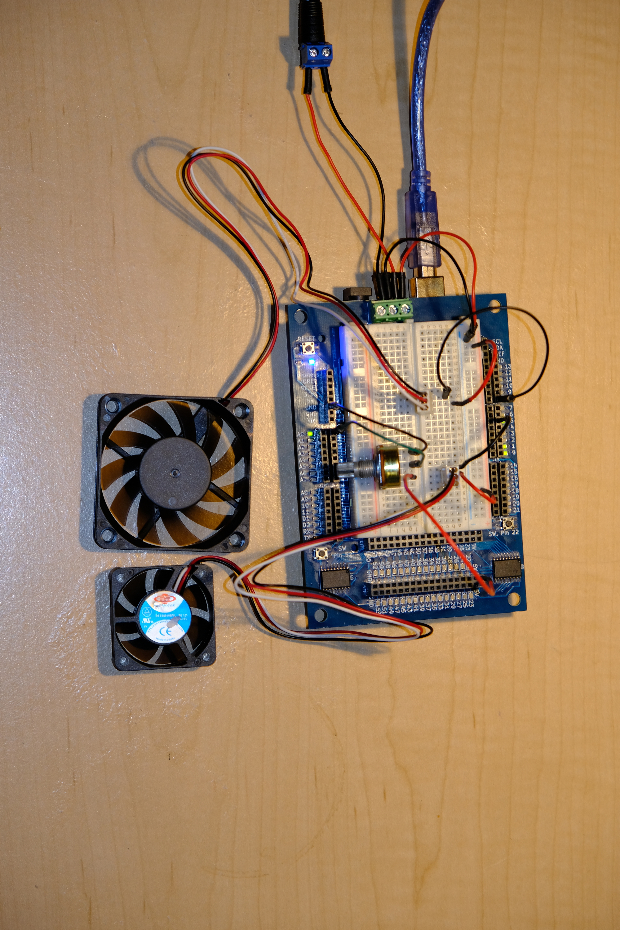
In the sample configuration a potentiometer was wired up to one of the Arduino analog inputs and used to control the speed of two fans.
This board has not yet been fully tested, nor has it been used enough for possible bugs to come out. Some issues that will need investigated:
As noted above, I do not plan on making more than 10 of the Revision 1.0.0 Mega LED & Power Proto shields. However, depending on demand, I may make an updated version. Here are some of the improvements and bug fixes under consideration:
Another idea is making a version for the Arduino Uno. It may also be possible to make a combo Uno shield and a Mega expansion shield, letting the two work as a pair on a Mega. This would make it easier to use just half of it on an Uno. And you could remove half at a time from the Mega, which would make pulling the thing off a lot easier.
© David C. Hunter, 2019
fb [at} dragonsdawn {dot} org
![]()
