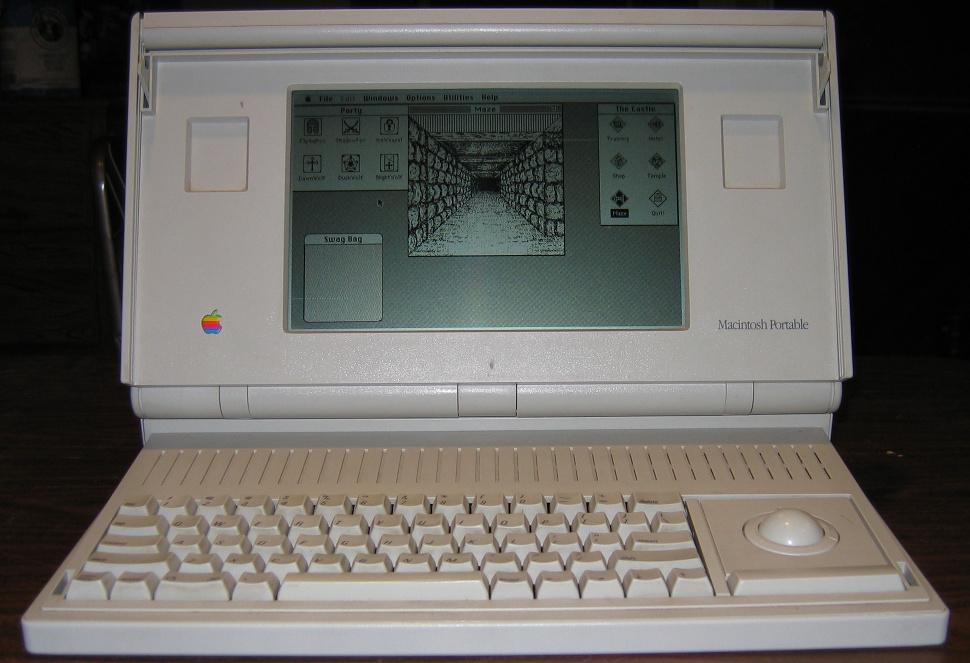
Notes
These instructions have not been tested with the first model of Macintosh Portable, Model M5126. There were some changes to the motherboard in the later model so these instructions may or may not apply.
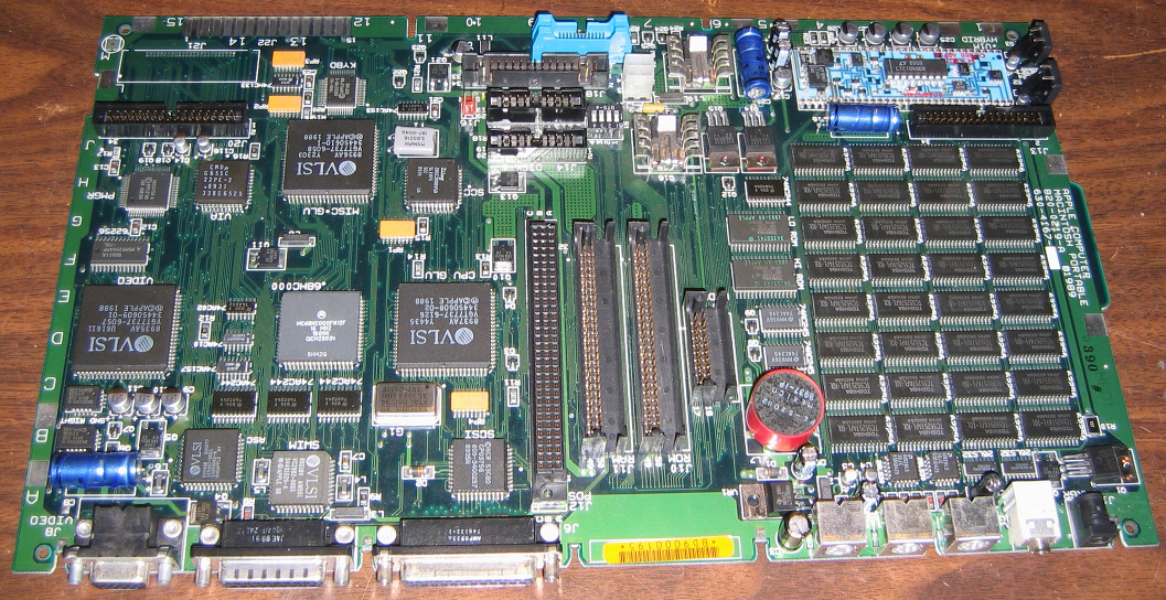
The capacitor designations used are marked on the circuit board. They are assumed to be the same on every board but this has not been verified.
Diagnosis
Note that only one machine was used in making this diagnosis and symptoms may vary from machine to machine. Aging capacitors is likely a problem in many nonfunctional Macintosh Portable computers. The best way to diagnose bad capacitors is to remove some of each type used in the system and test them.
- Most of the time the machine would not turn on.
- Occasionally it would turn on when the main battery was removed and the nine volt battery was reinstalled. When it turned on it have a sad Mac face and a couple Hex codes. The codes were decrypted using this page. About half the time the hex codes did not match any known errors. The rest of the time they indicated problems with the power manager.
- Several capacitors were removed and tested. Some were within acceptable limits while others were not.
*Really, that is what the capacitance meter said.Capacitor Listed Value Tested Value C28 48uF 53uF C8, C16, C20 470uF OUCH* C19 100uF 104uF C3 200uF 231.2uF C116 10uF 0.3nF C4 1uF 1.4nF - While not all the tested capacitors failed it is suggested that you replace all the non-monolithic capacitors. The provided Bill of Materials assumes you are doing so.
Skills Required
- You will need to be able to properly remove and reinstall the motherboard in the Macintosh Portable.
- You will need to be able to solder and desolder through hole and surface mount components with no more than two leads no closer than 0.1 inch.
Tools & supplies
Required
- Soldering Iron. Low quality soldering irons may not provide adequate performance for this task.
- Solder Wick
- Syringe filled with liquid rosin flux
- Solder. Use a solder approved for use in your area, suitable for use on electronics, and suitable for your soldering iron.
- Small brush
- Electronics grade isopropyl alcohol
Strongly recommended
- ESD work area. Electrostatic damage to your computer may occur if you repair it without using proper ESD precautions.
- Microscope with light source setup for use in soldering.
Suggested
- Solder sucker
- Isypropyl bath or large sonic cleaner.
- Pressurized air duster
Bill of Materials
| Part | Description | Footprint | Digi-Key Part # | Qty |
| C2, C6, C18, C19 | 100uf, 25V | 0.11" Through | 493-1548-ND | 4 |
| C3 | 220uF, 25V | 0.15" Through | P12383-ND | 1 |
| C4, C5, C15, C24 | 1uF, 50V | 0.18" Surface | 493-2130-1-ND | 4 |
| C8, C16, C20 | 470uF, 25V | 1.1" Through | 4217PHCT-ND | 3 |
| C9-C11, C17, C22, C25-C28 | 47uF, 16V | 0.256" Surface | PCE3340CT-ND | 9 |
| C14, C116 | 10uF, 16V | 0.18" Surface | 565-2534-1-ND | 2 |
Notes
- C16 and C20 originally were 16v but replaced were with replaced with 25v capacitors in order to simplify the bill of materials. This will not adversely effect the performance or lifetime of the repaired computer.
- The footprint is the actual measured lead spacing. The specified Digi-Key parts may not have the same spacing but are close enough.
- You may want to order a few extra of each part in case some are lost or damaged during installation.
Procedure
- Remove the motherboard from the unit.
- Clean the board. Dust it off using a suitable air duster. Use a small brush dipped in isopropyl alcohol to clean the area around the capacitors listed in the BOM. Sometimes a residue will build up around some capacitors. Be sure this is fully removed as it may interfere with soldering and desoldering.
- Remove the capacitors listed in the BOM. Use the soldering iron and solder wick to remove the surface mount capacitors. A solder sucker may help with the through hole capacitors but they can also be removed with the iron and wick. If the iron fails to melt all the solder make sure it is making proper contact. A very small bead of solder on the iron may help. If it still fails to melt the solder remove the iron, let the board cool, increase the temperature of the iron, and try again. Do not force the parts off as doing so can tear the contact pad off of the circuit board. Remember that the hot iron can easily damage other parts of the board, especially the plastic connectors.
- Clean the capacitor mount points with the brush and isopropyl alcohol. Use the soldering iron & wick to remove any excess solder on the pads. Make sure the pads are lightly tinned.
- Install the new components as listed in the Bill of Materials. Treat the connections with flux prior to soldering. Make sure the the positive and negative terminals are properly aligned.
- Clean off the leftover flux using the brush and isopropyl alcohol. If possible clean in a large isopropyl bath or sonic cleaner. Make sure that all residual flux is removed. Dry board.
- Reassemble computer.
