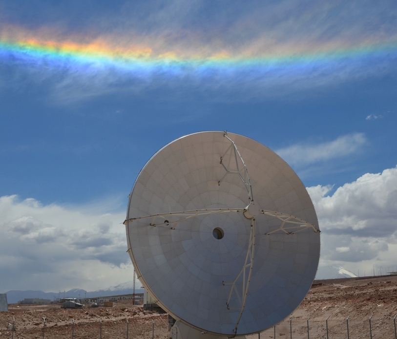
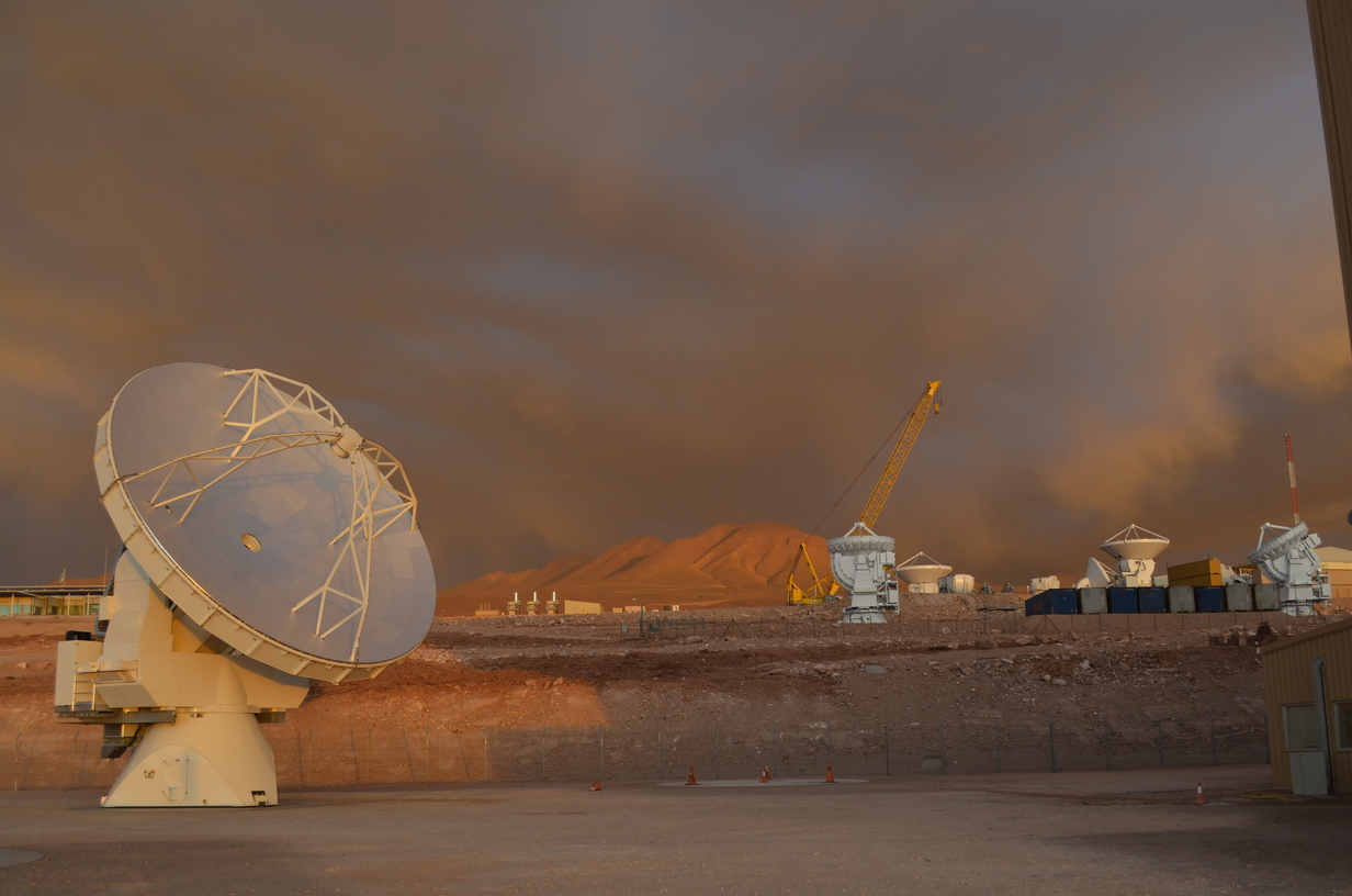
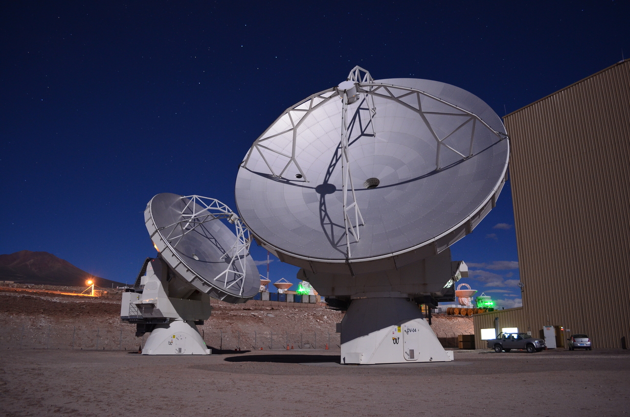
The Atacama Large Millimeter Array (ALMA) is a network of antennas spread across Chajnantor plateau in Chile. Like other interferometers, they operate as a single telescope. Being located at 5000m (16400ft) it has lower atmospheric interference than other ground based radio telescopes.
- Frequency:Selected bands between 84 and 950GHz
- 66 Antennas
- 12 & 7 meter antenna diameters
- Longest baseline: 16km
- Construction: 1997-2013
The Atacama
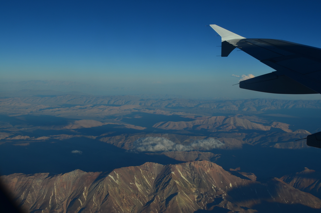
ALMA is located deep in the Atacama desert. Workers fly into the city of Calama, then take a couple hour bus ride to the site itself. While some parts of the Atacama have no recorded precipitation, most of it does get a little. There is a little snow in the mountains in the winter, and the rare rain storm will cause flash floods.
You can find more about living in Chile here.
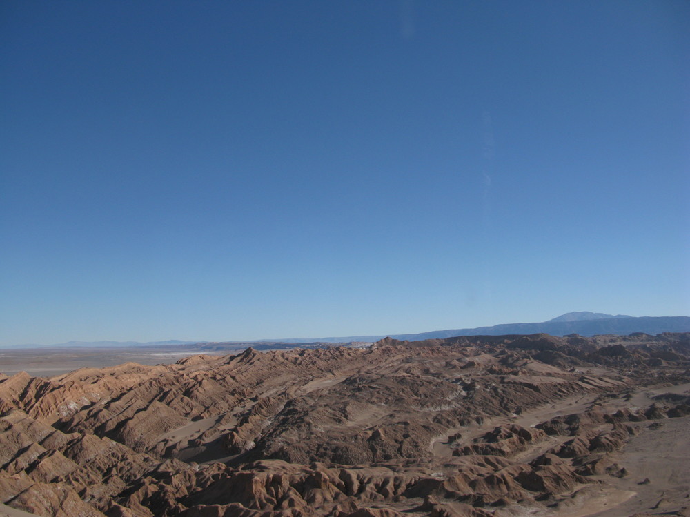
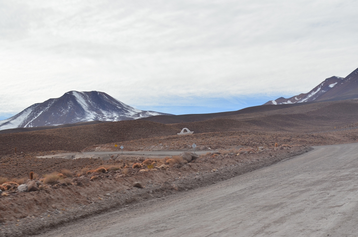
On the way to the site you pass by Valle de la Luna (Valley of the Moon).
This is just one of many interesting places to visit in the Atacama. Another, The Conchi Viaduct, is documented by the same author at Scary Bridges.
San Pedro de Atacama
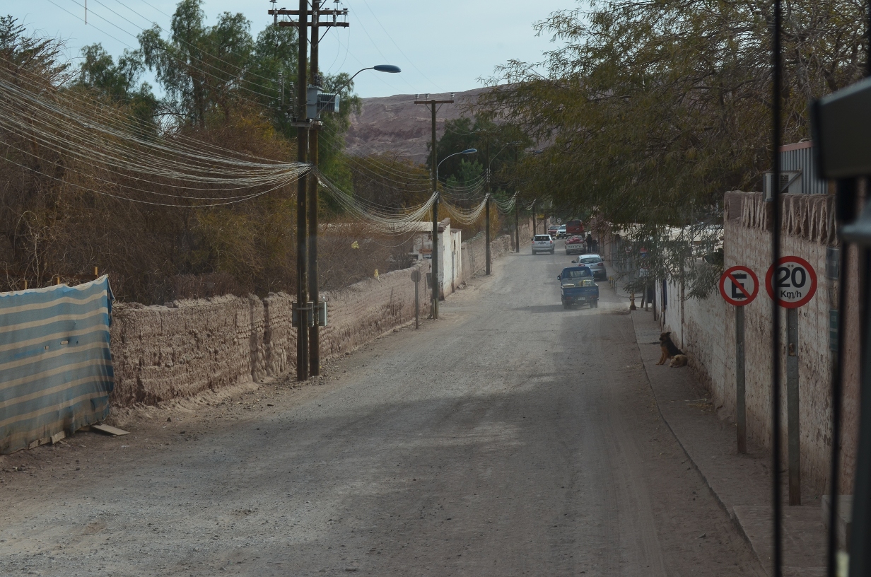
San Pedro is the closest village to the ALMA site.
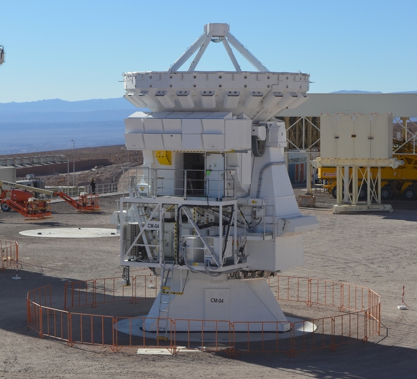
North American antennas
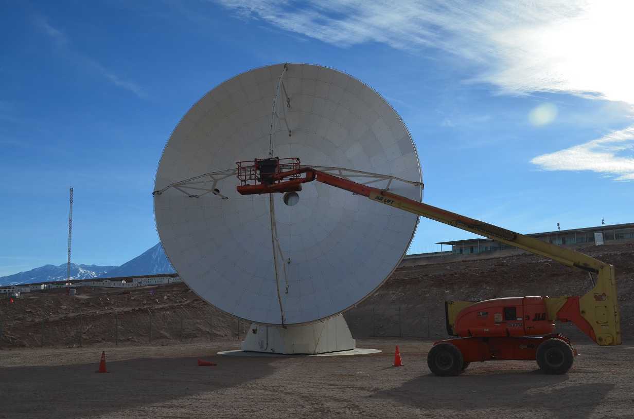
These are 2 of the 25 antennas contributed by NRAO. They were built by the Vertex division of General Dynamics.
Several designs
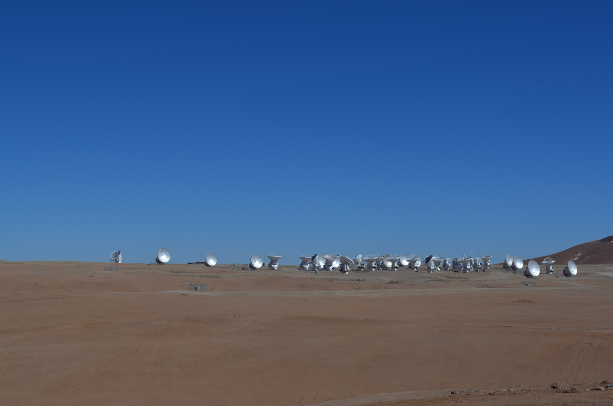
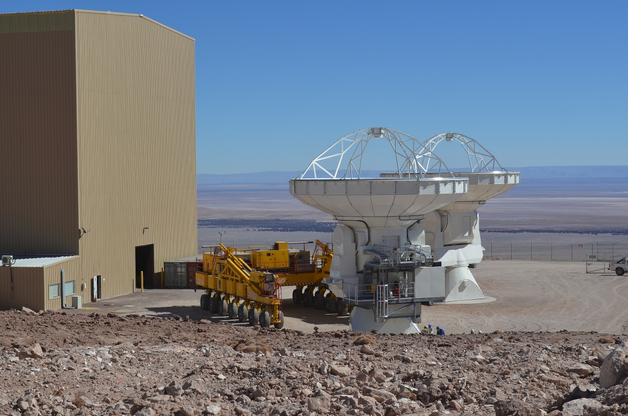
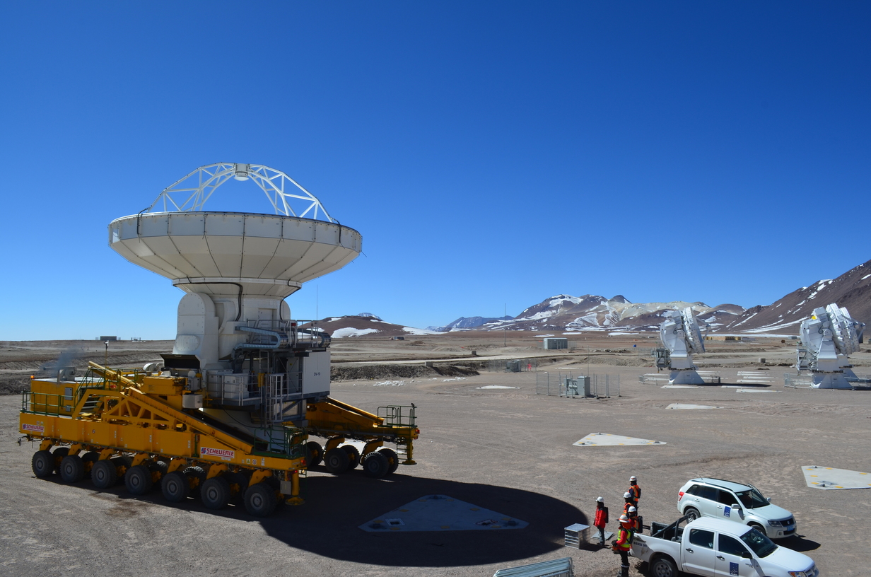
The United States, Europe, and Japan each contributed their own antennas. The US antennas is to the left. The Japanese antennas are the 2 closer antennas up the hill. The European antennas are the furthest up the hill.
At night
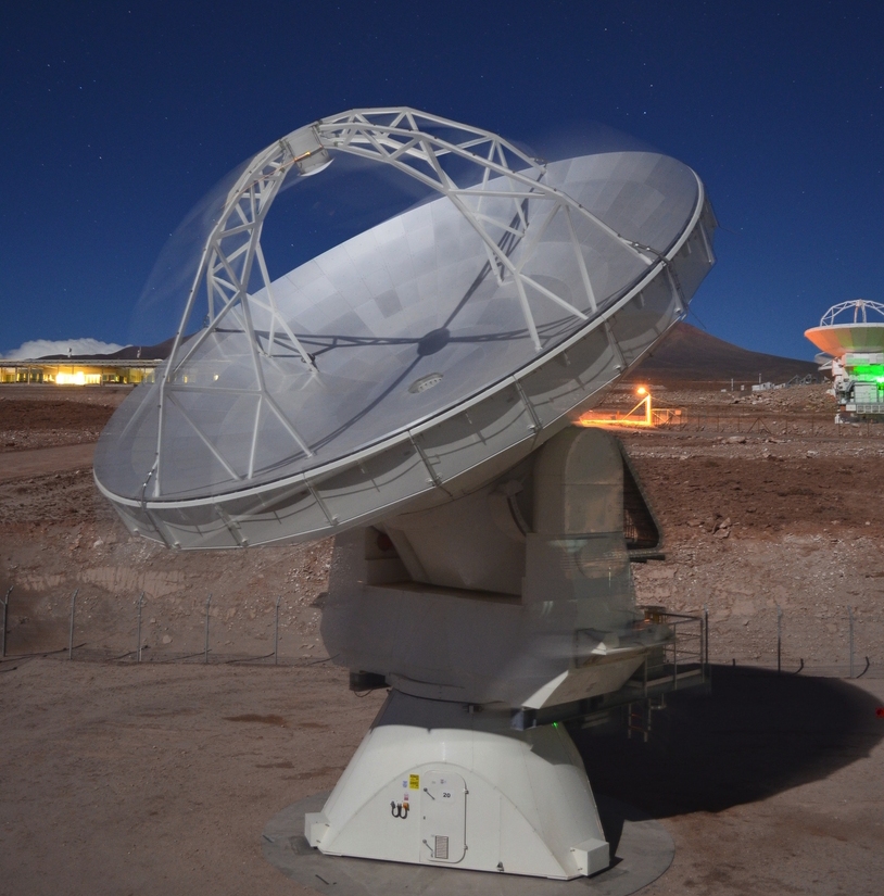
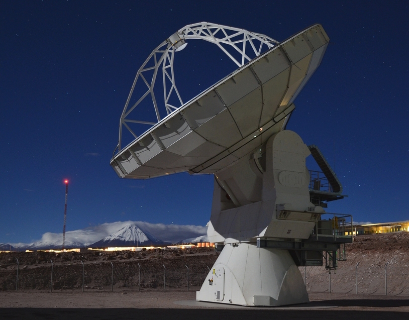
Some of the best pictures are taken when there is a full moon.
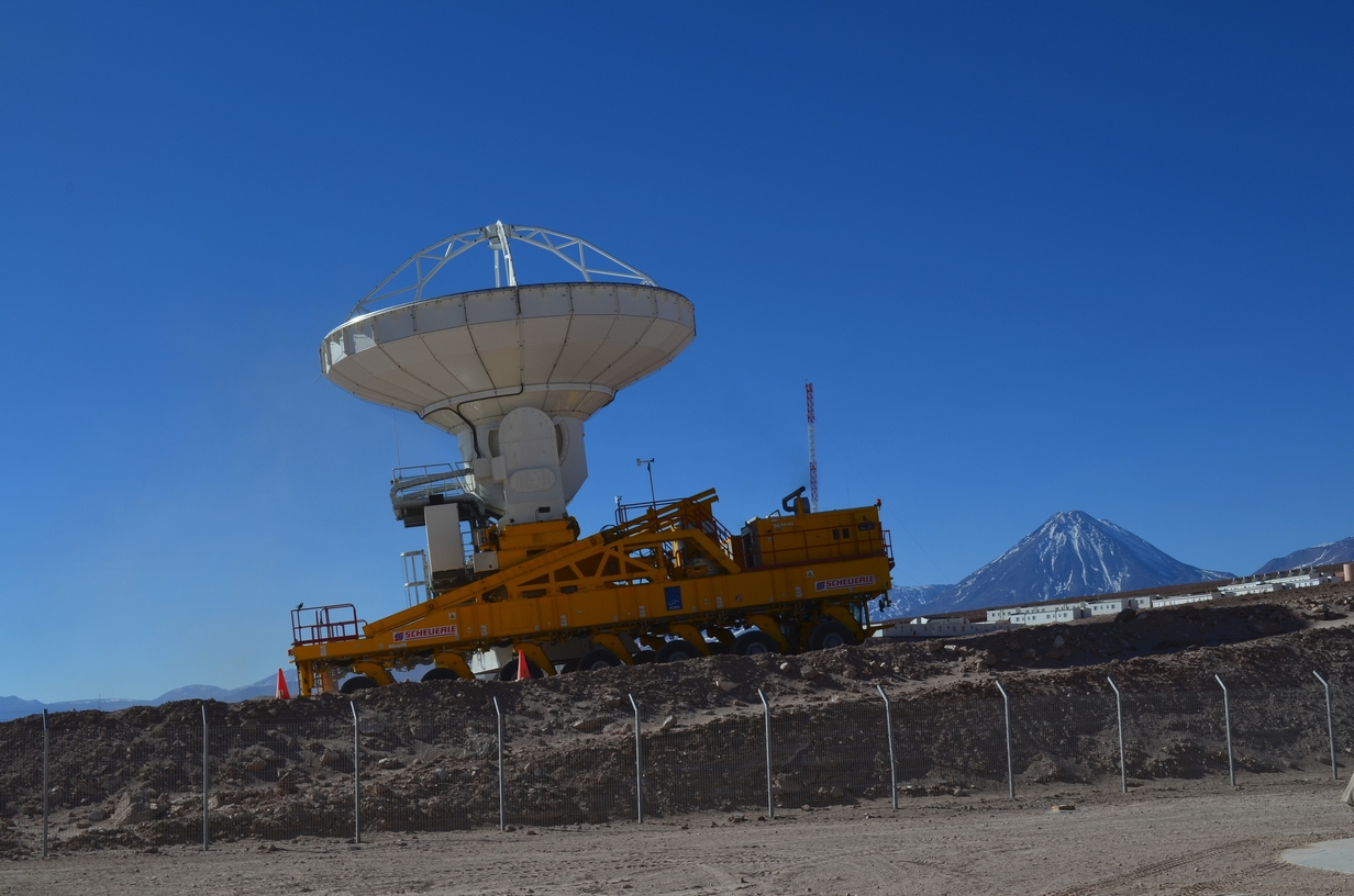
One of the antennas just as it starts moving.
The mountain in the background is Licancabur, a 5400m (17,717ft) volcano.
ALMA 7m antenna
The Japanese contributed 4 12m antennas and 12 7m antennas to the project. One reason for the smaller size was to allow a few antennas to be packed closely together. They are also less expensive.
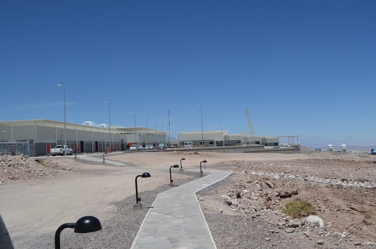
The OSF technical building.
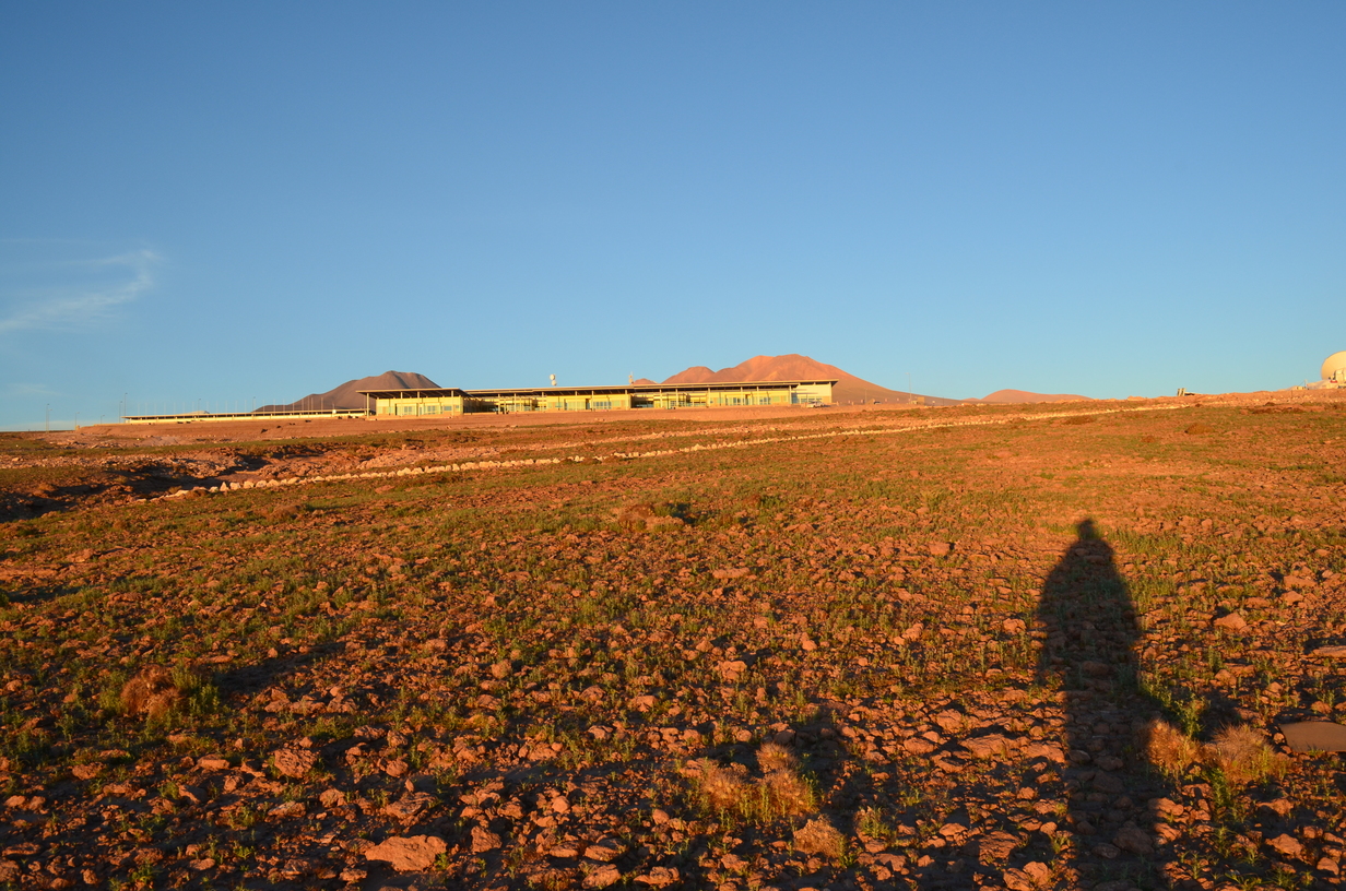
Most of the operations and support is conducted at a lower elevation site, and the antennas are then moved to the high site. This is a technical building at the Operations Support Facility (OSF).
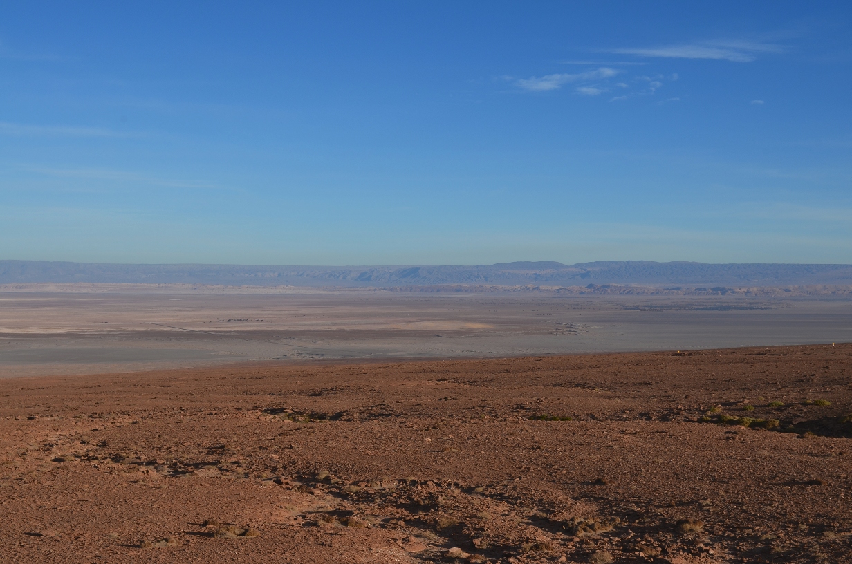
View from OSF
Since the OSF is partway up the mountain there is a nice view over the valley. San Pedro is just outside of view to the right.
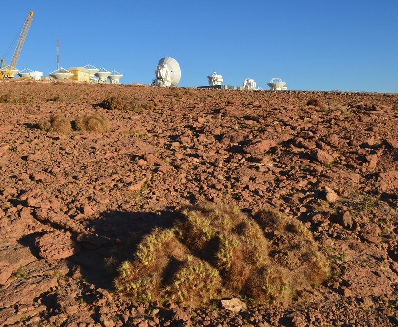
A cactus
There are a few cacti that manage to survive in the area.
OSF after a rain storm
A rain storm reviled that there was a remarkable quantity of dormant vegetation - not just the cacti. Not much compared to Seattle, but there is some.
Cactus Canyon
An important part of working at a remote site is making the best of it. While the OSF appears to be desolate, a little searching will reveal interesting places to hike. This narrow canyon is a short hike away, and can provide a nice break during the eight day work shift.
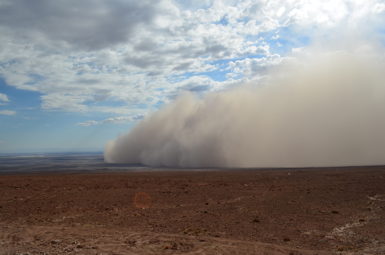
Sandstorm
There are a few sandstorms...
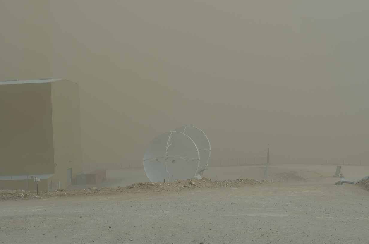
In the storm
The sandstorms vary in intensity. This was one of the worse ones, causing a small amount of damage.
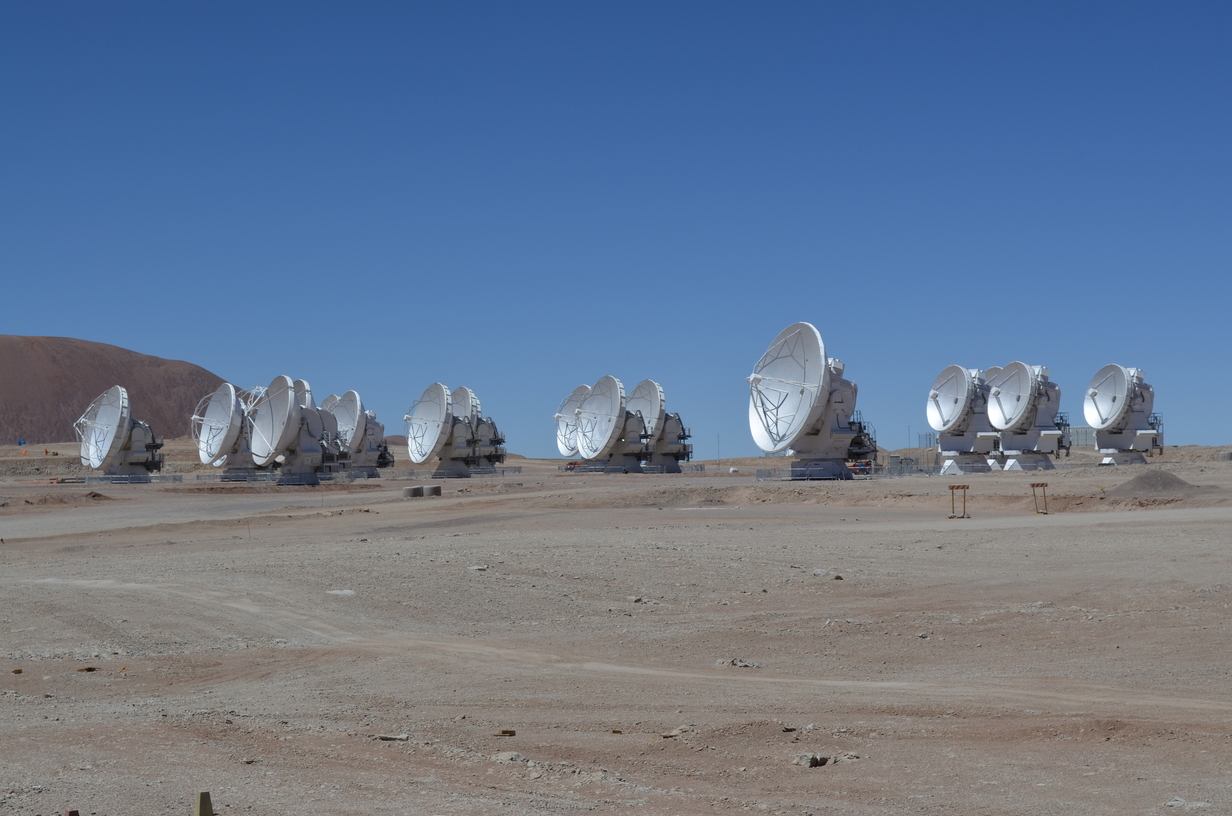
The array
The array itself is located high in the mountains. This photograph was taken when only a few of the antennas were ready.
More antennas in this photo, but still not the entire array. This was taken during the maintenance and construction time, so the antennas are not setup as a single array.
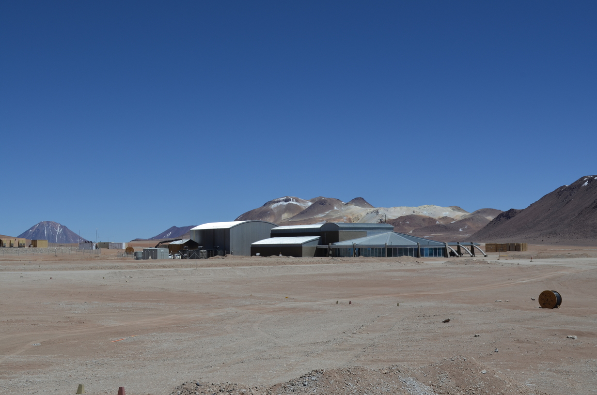
The AOS Technical building
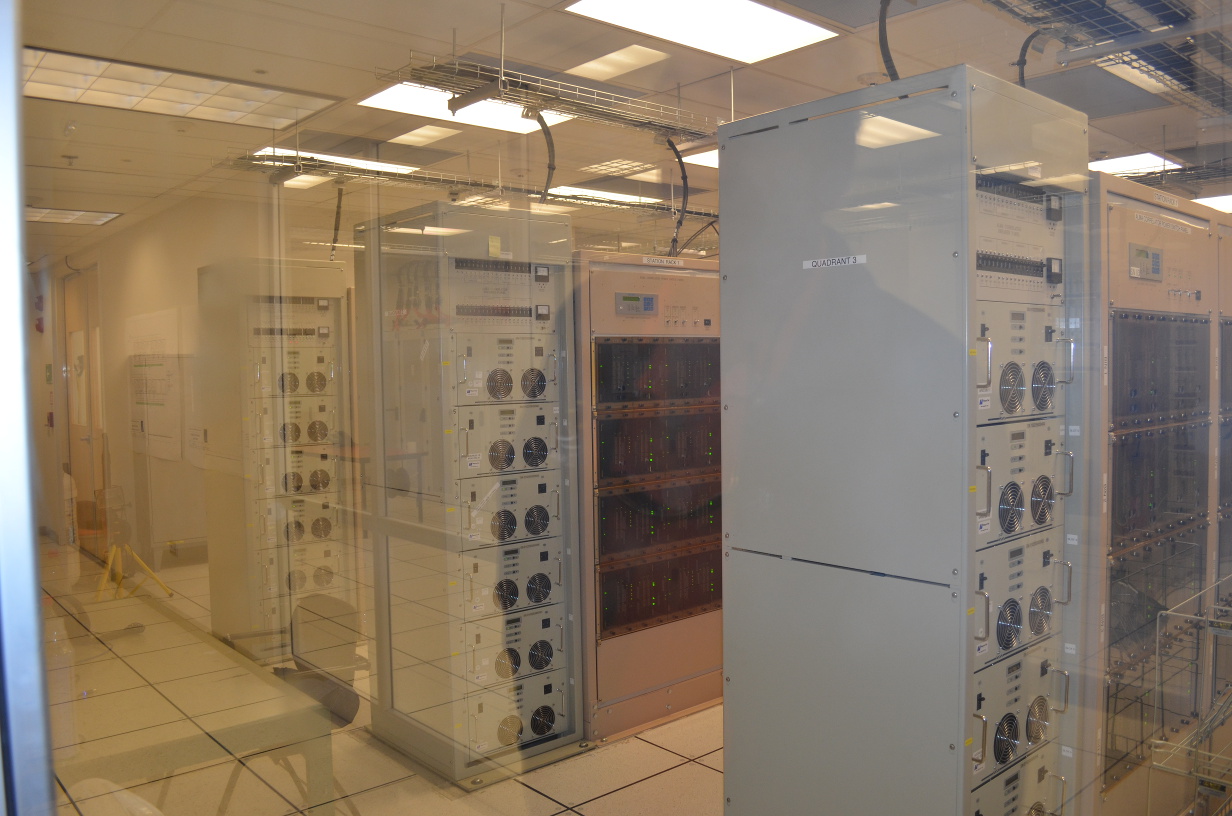
This building houses the computers and correlator that control the array.
On the outside the correlator looks about like any other server room, but is is actually custom built. It uses thousands of FPGAs to correlate the data from all the antennas as it comes in.
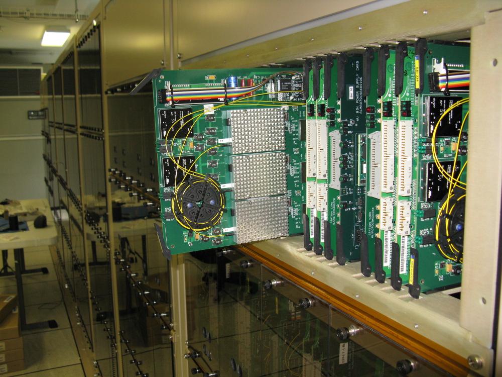
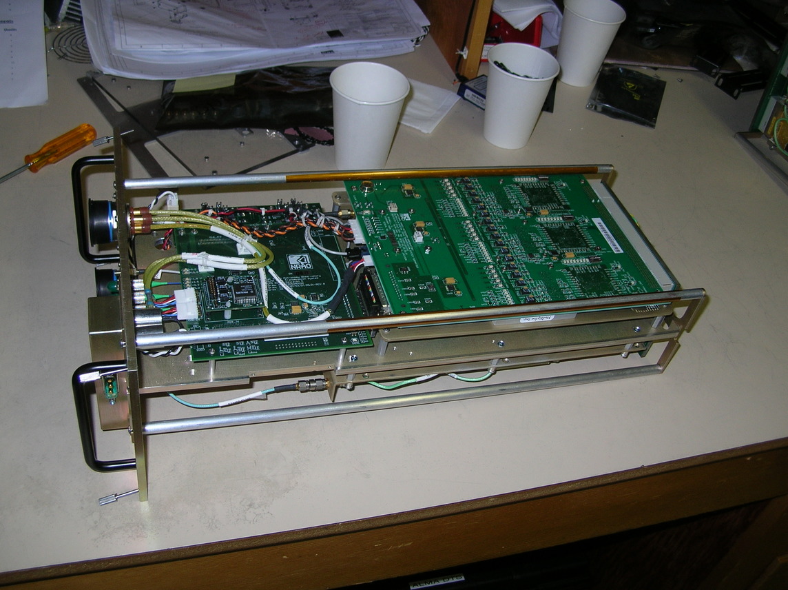
One of the data receivers (DRX) inside the correlator. Each card has 3 OC-192 half transponders. Each half transponder receives almost 10GB/s, so with 4 DRXes per antenna, the raw data rate is almost 120GB/s. When the system was designed in the 2000s, this was an extremely high data rate.
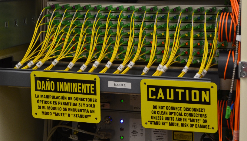
The antennas are synchronized using a high precision central clock which sends a signal to every antenna over these fiber optic cables. Thermal expansion of the fibers over their several kilometer run is a problem. The line length corrector units measure that expansion and (very slightly) stretch the fiber to compensate.
Bamboo
The entire area is barren. The only plants that could be found were a few potted plants in the lobby of the technical building.
AOS HVAC
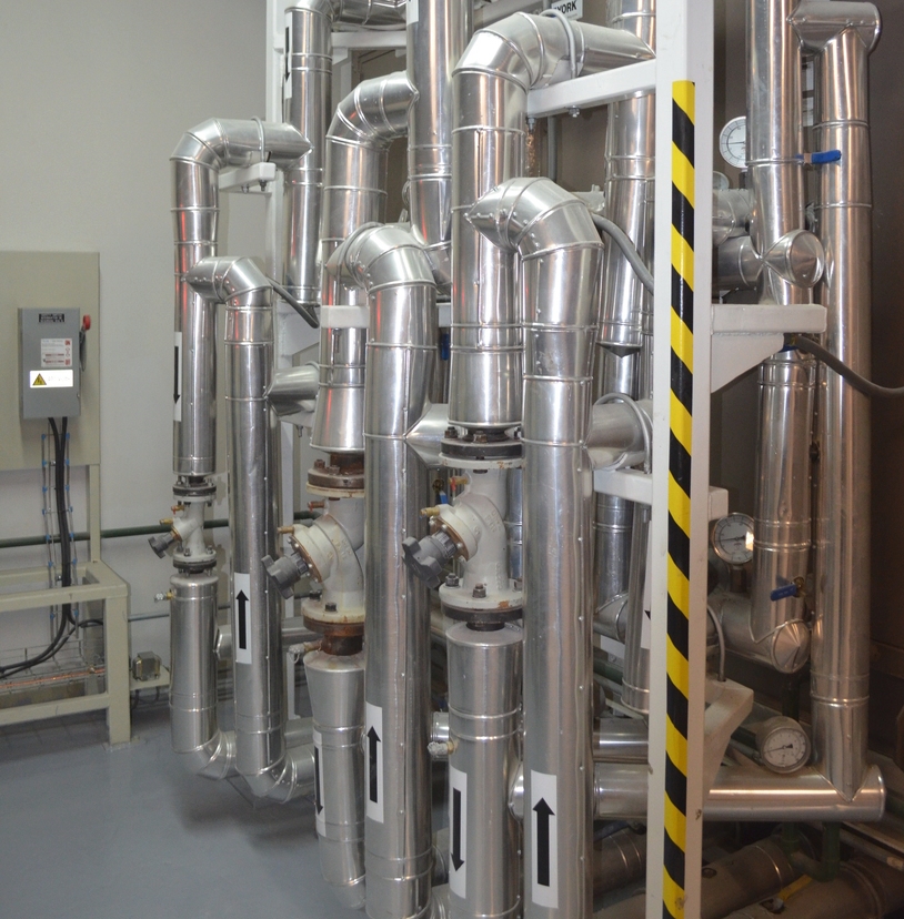
The computers and correlator require a large amount of cooling, which is especially difficult due to the low air pressure at high altitude. This is a small part of the site HVAC system.
Moving an antenna.
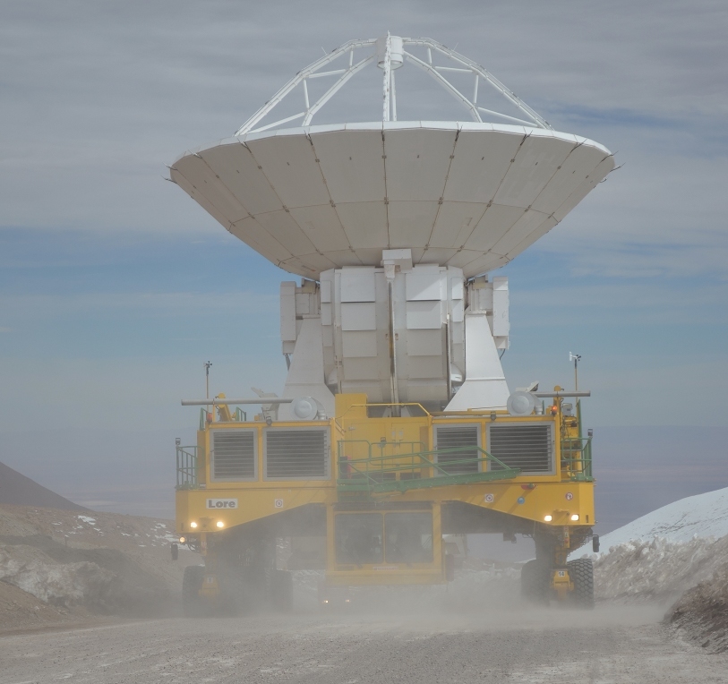
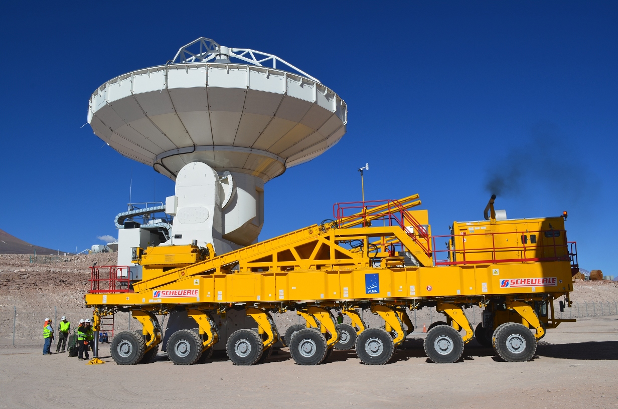
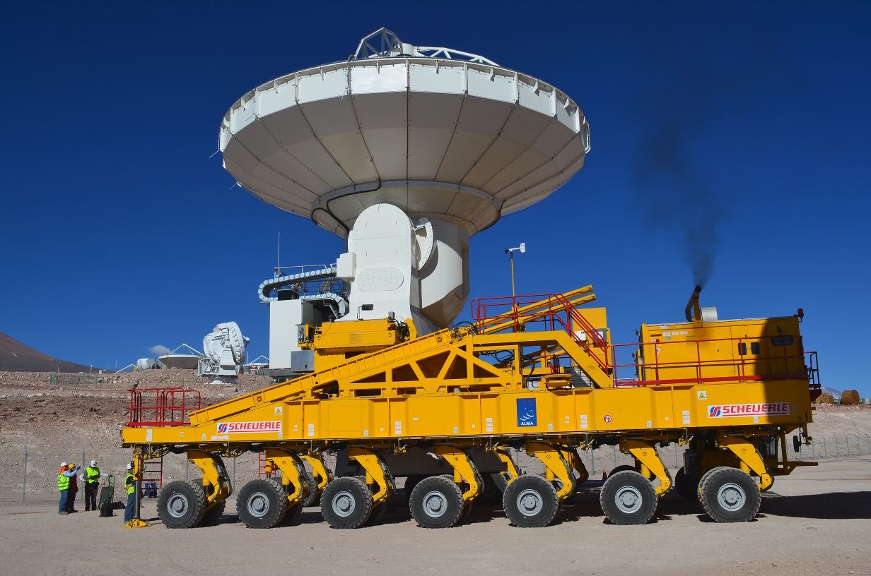
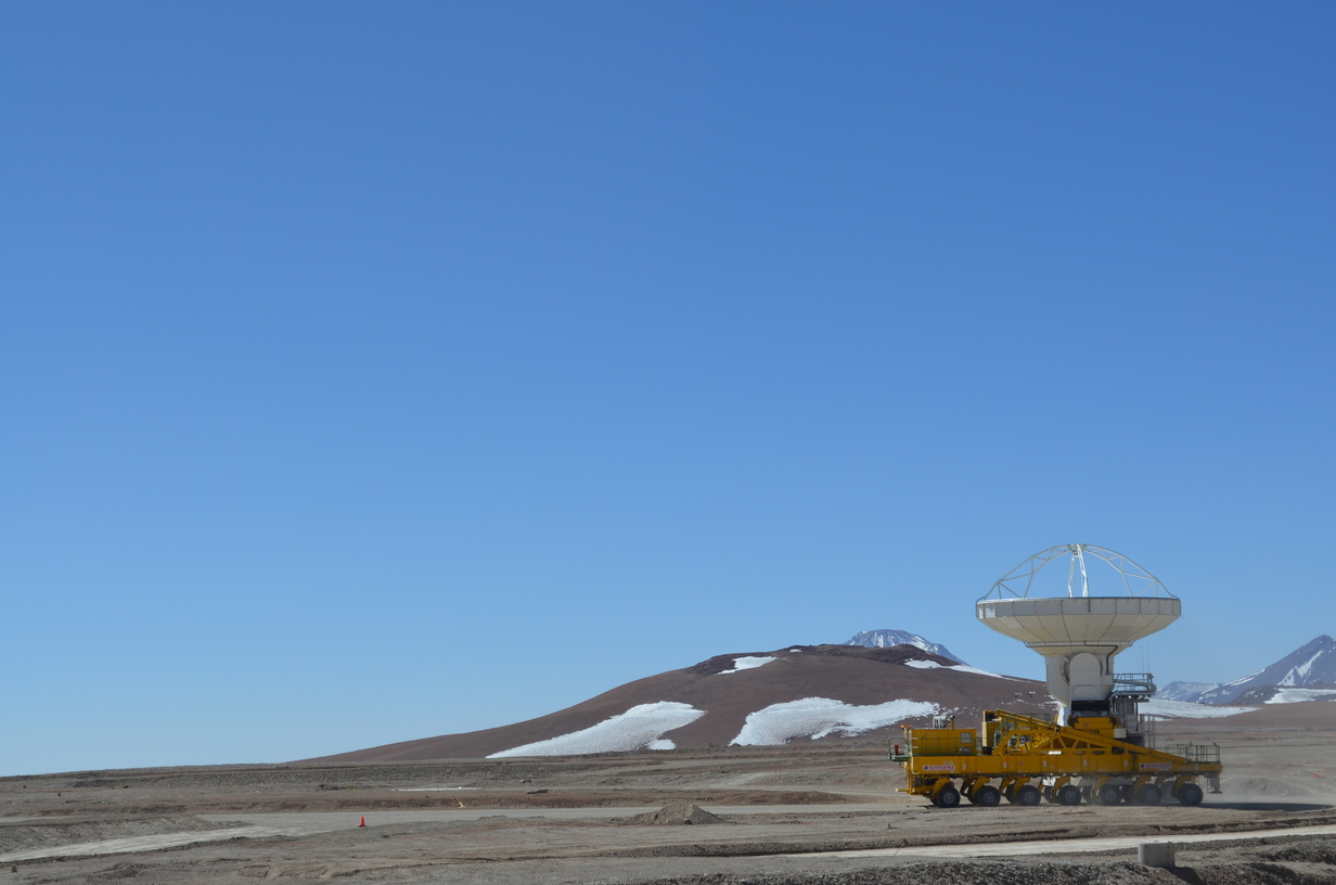
Like antennas at the VLA, the ALMA antennas can be moved via a custom build transporter. Unlike the VLA, the transporter is not rail based. It is U shaped, has 28 wheels, and drives on a very wide dirt road.
Picking up an antenna.
The transporter approaching an antenna to pick it up.
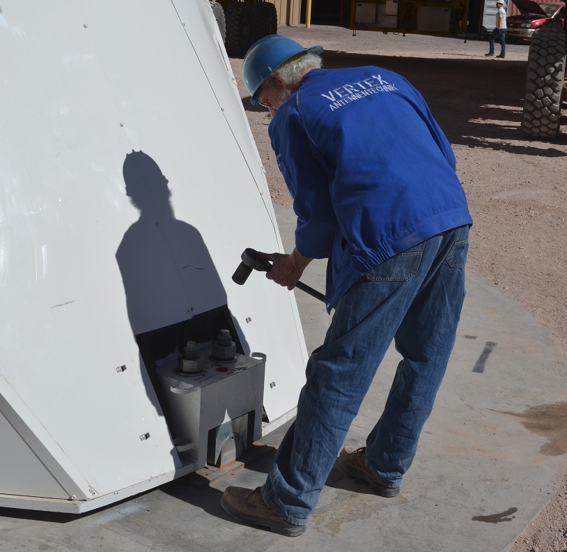
Unbolting an antenna
The antennas are held down with 6 large bolts, two at each corner.
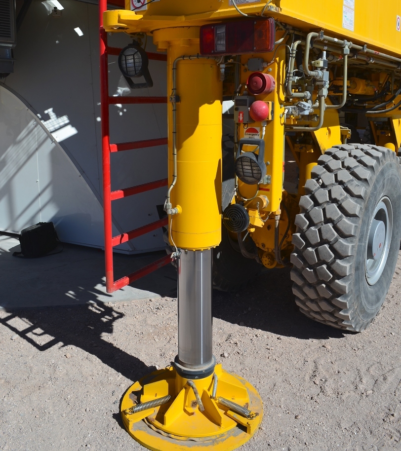
Hydraulic lifts are used to support and stabilize the transporter as it lifts the antenna.
Lifting an antenna
There are two lift points on either side of the antenna, at the bottom of the yoke. The transporter lifts the antenna off of the antenna pad.
Lifting an antenna
The antenna is thin slid up a ramp into the transport position.
Driving off with it
Once the antenna is secure the transporter then drives off.
On the way
An antenna sneaking its way up the mountain...
At the AOS
It is a long drive to the Array Operations Site (AOS). It is a days work for a transporter to pick up an antenna at the OSF, drive it up to the AOS, and come back to the OSF.
Finally there!
An antenna is placed on the waiting pad at the AOS.
Working on the hexapod
At the apex of the antenna is a hexapod, a custom device that provides for X, Y, and Z movement and rotation. It precisely positions the subreflector to focus the beam on a receiver.
Cable wrap
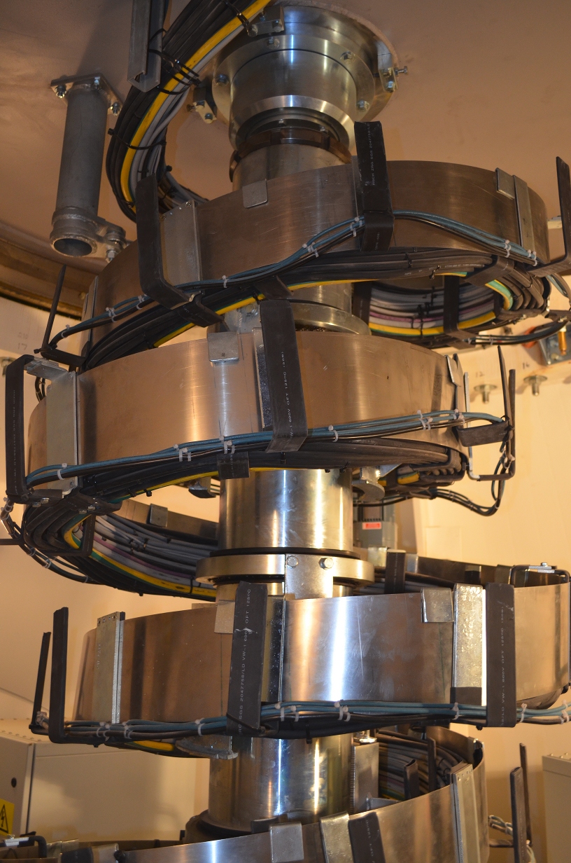
This cable wrap allows the antenna to rotate without damaging the cables. The cable wraps vary in design between the different models of antenna. This one is in the North American / Vertex antenna.
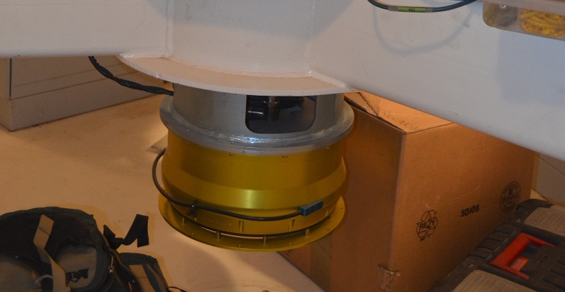
Fiber wrap
The yellow module is a fiber wrap. An optical timing signal is sent to each antenna to synchronize it with the master clock. This very precise signal is sensitive to polarization changes, and those can be caused by twisting a fiber along the longitudinal axis. The cable wrap would disturb the phase as the antenna moves. So the fiber wrap allows the antenna to rotate without upsetting the polarization.
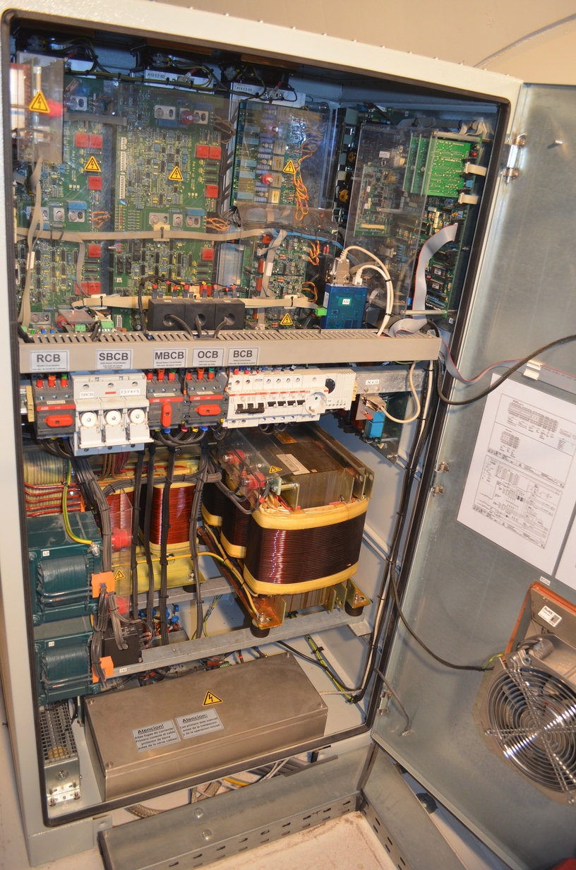
UPS
Each antenna has a three phase 15000VA continuous conversion UPS.
Caution: may be harmful or fatal if swallowed.
The Optical Pointing Telescope
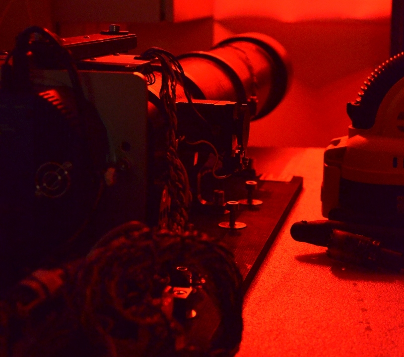
One of the tests done on the antennas used an optical pointing telescope (OPT) to verify antenna performance. It turns out that OPTs can look a little sinister if you catch them first thing in the morning
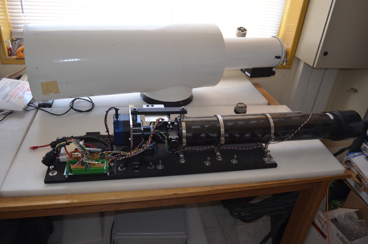
Another view of the OPT
A more normal view of the OPT and its enclosure. This time with normal lightning; the last photo was illuminated only by the red status lights on the nearby electrical box.
Receiver cabin
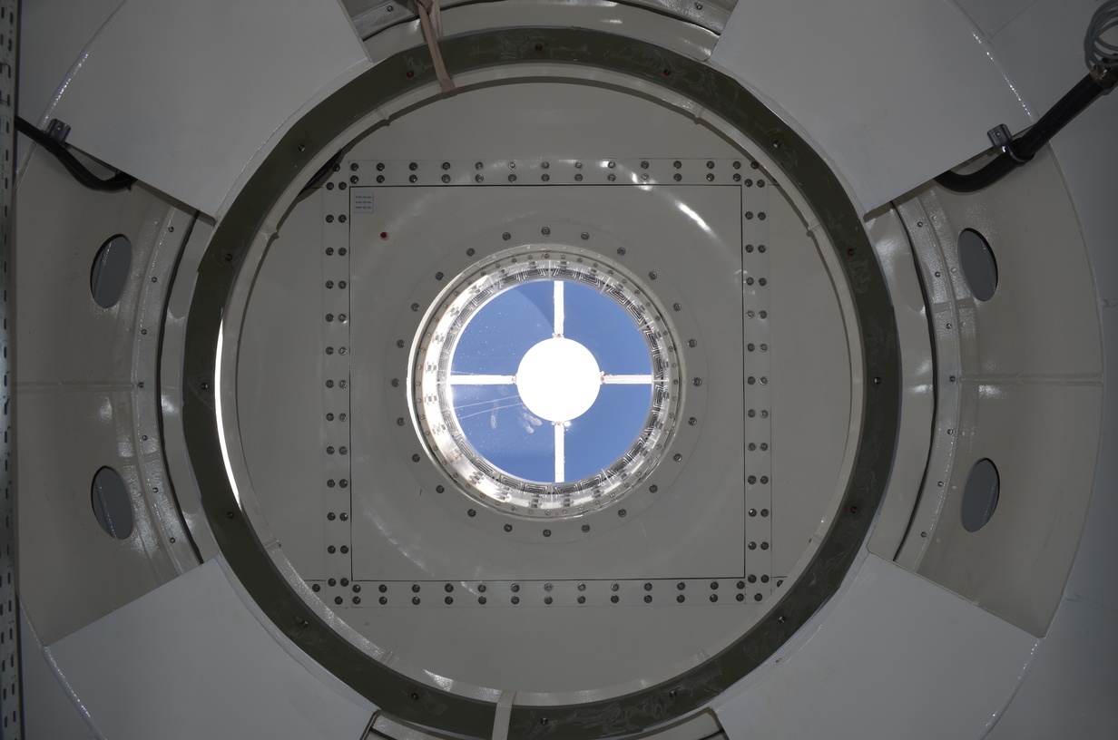
This is the roof of the receiver cabin, looking out of the bore. The front end receiver will mount on the gray ring. A thin membrane provides an environmental seal while minimizing interference with the signal. Most of the metal seen here is invar (and white paint), a special alloy with a very low coefficient of thermal expansion.
Front End Receiver
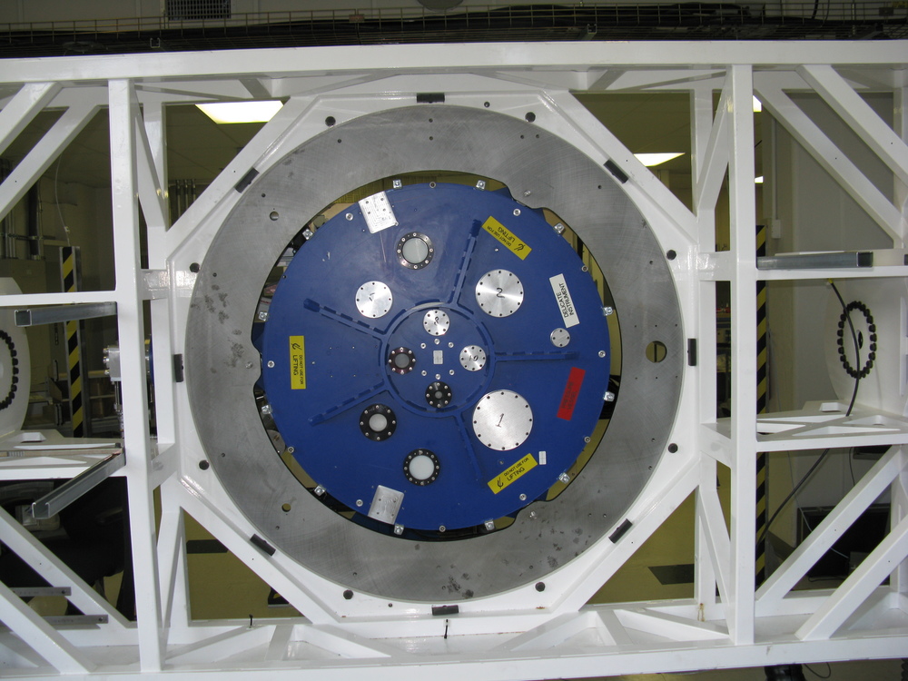
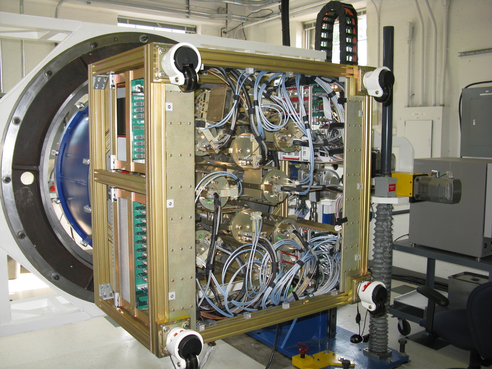
This is a front end receiver mounted in a test frame at the Charlottesville lab. When installed in the antenna the face shown will be aligned to point out of the bore hole. The various circles are where the receiver cartridges will be installed.
Front End Electronics
This is the bottom side of the front end receiver. The signal is down converted to 12GHz and sent to the back end electronics racks. There it is down converted again to 4GHz, then digitized and sent to the correlator.
Detail of receiver
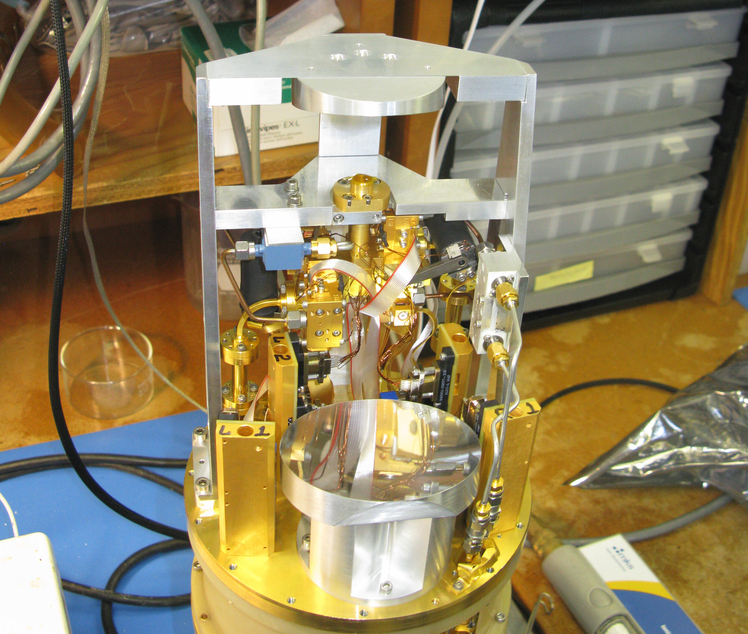
This is one of the receiver cartridges. A couple small subreflectors focus the beam on the receiver itself. When operating the upper stage of this unit will be cooled to a few degrees kelvin! (For any U.S. based laypeople that might have wandered in, that is colder than -450° F).
Receiver circuitry
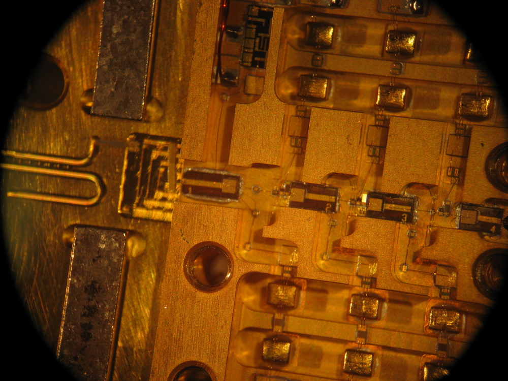
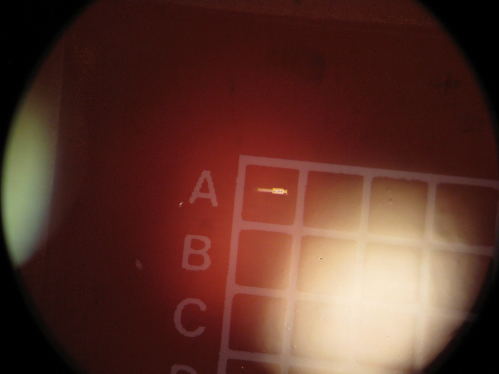
This is part of the receiver as seen under a microscope.
Detail of circuitry
Zooming in we can see part of the circuit. While parts of the receiver are made by machine, a large portion of the assembly, including the wiring seen here, is done by hand.
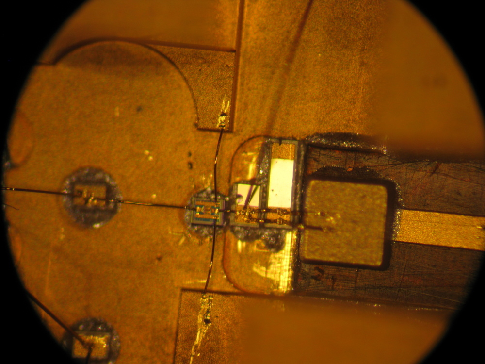
Micro parts
This is one component awaiting installation.
Alma DTX
This is an Alma Data Transmitter (DTX). It contains a 4GHz digitizer and 3 10GB fiber transmitters. Each antenna uses 4 of these to send the data back to the correlator. Each fiber transmitter sends on a slightly different frequency, allowing the 12 signals to be optically multiplexed onto a single fiber.
Some of the custom assemblies in this module were also used in the refit of the VLA, saving on design and manufacturing costs.
Conclusion
ALMA construction was a good project to work on. I was sad to leave, but the nature of construction jobs is such that you work yourself out of a job.
Last Update: Nov 2018; added photo of DRX.
© David C. Hunter, 2014-2018
fb [at} dragonsdawn {dot} org


