The VLA
The VLA is located on the planes of San Augstin in New Mexico. They provide a large, flat, and high altitude area that is well suited to the operation.
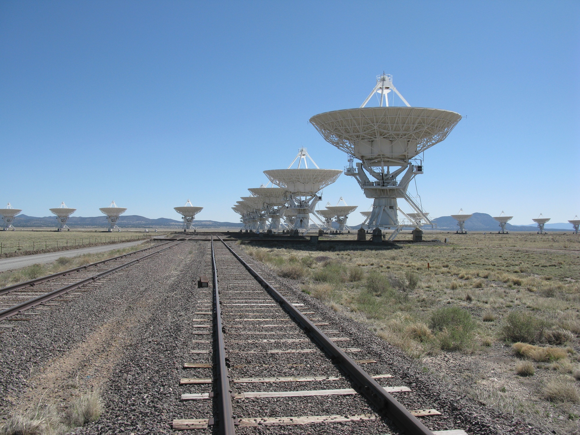
The Very Large Array (VLA) is a large network of antennas that operate as a single telescope.
The VLA
The VLA is located on the planes of San Augstin in New Mexico. They provide a large, flat, and high altitude area that is well suited to the operation.
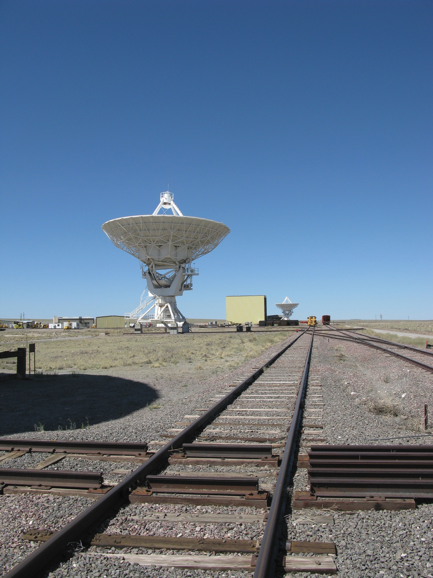
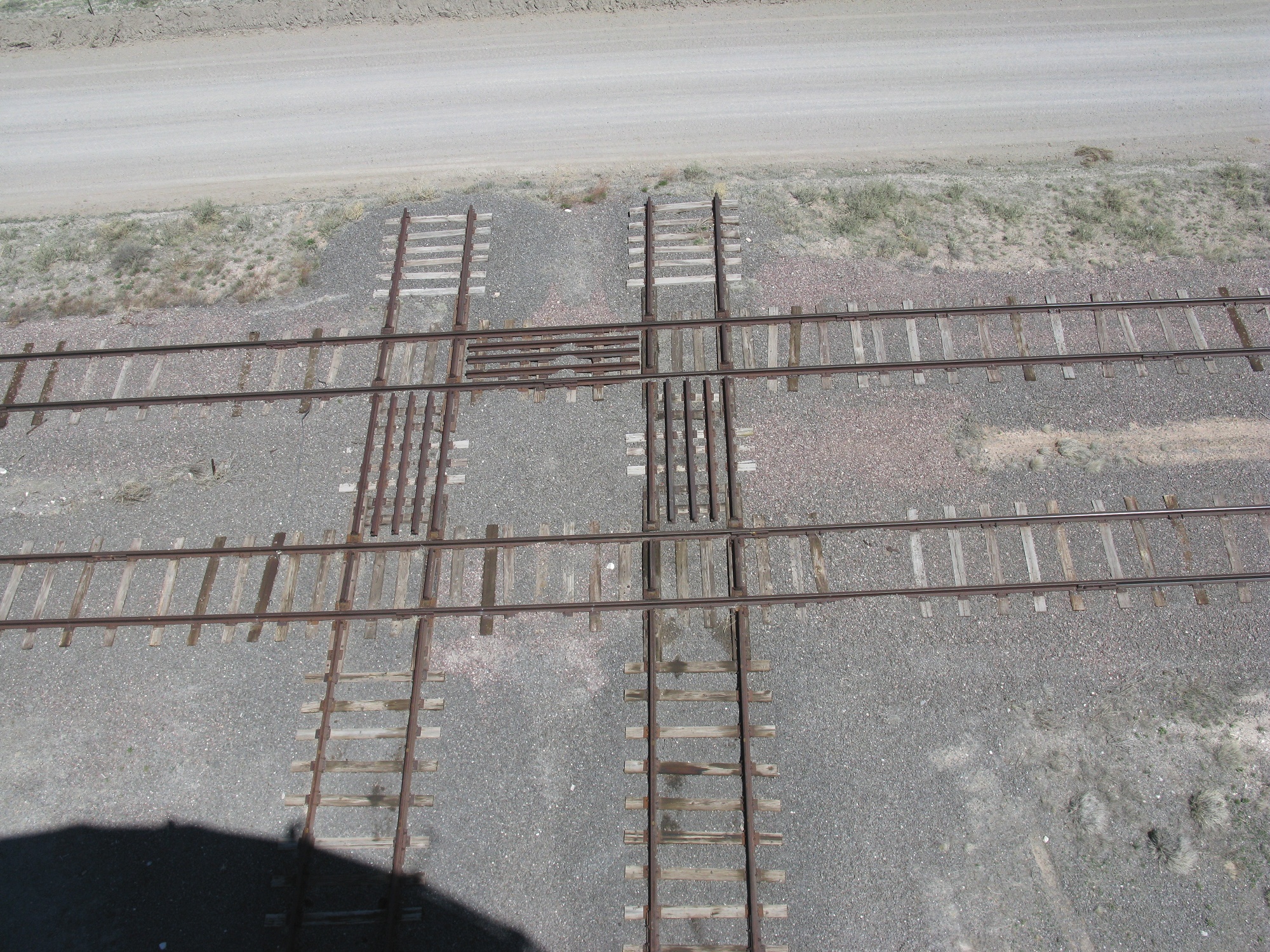
Railroad Track
A custom built transporter regularly moves the antennas around on a double railroad track. The transporter is unusual in its ability to make a right turn. It will stop at the cross track, lift itself up with some hydraulic feet, turn the bogies 90 degrees, and sits back down. This was substantially less expensive than using traditional switch tracks for every antenna pad.
It is hard to respect the size of these antennas without walking underneath them.

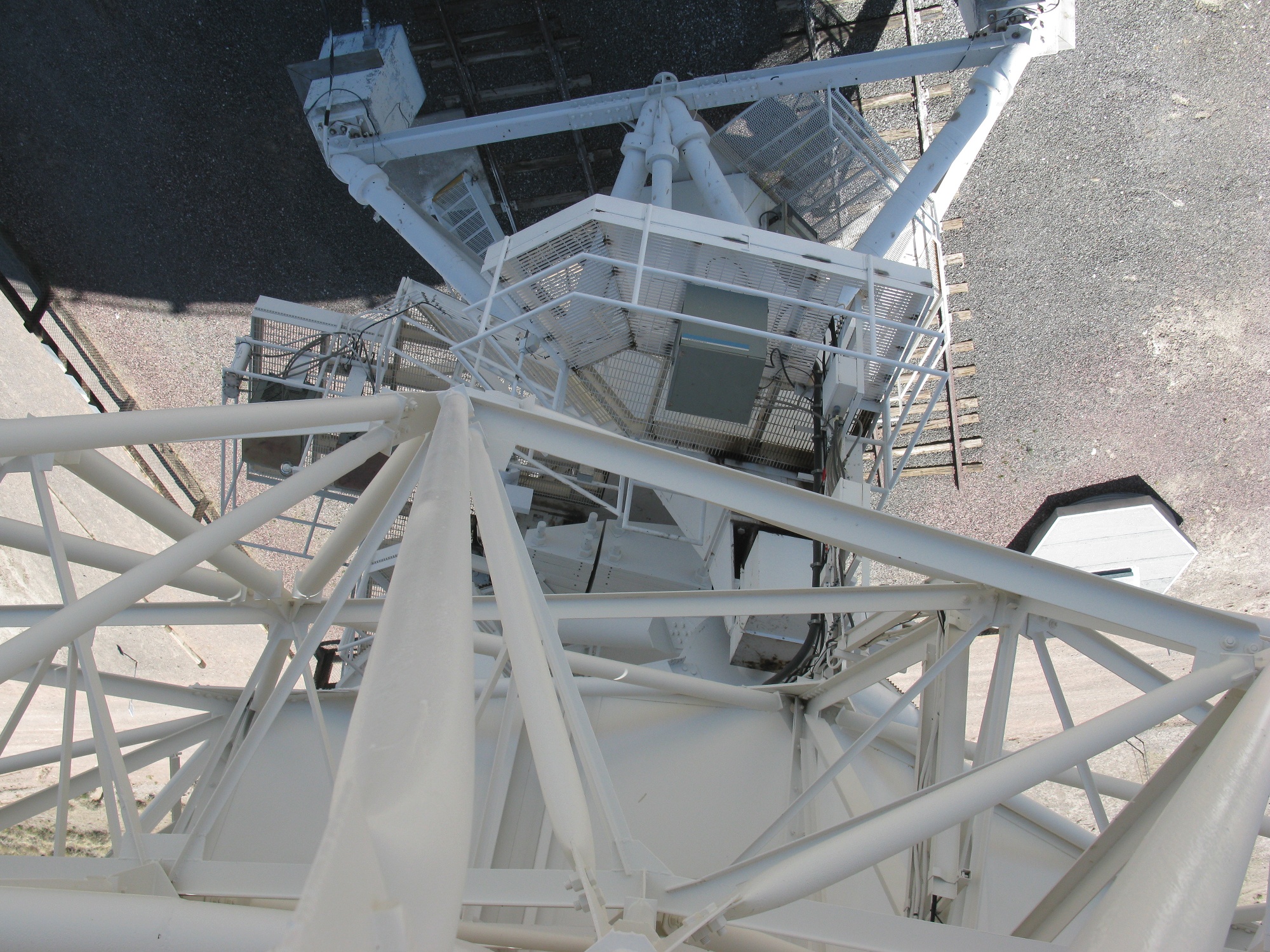
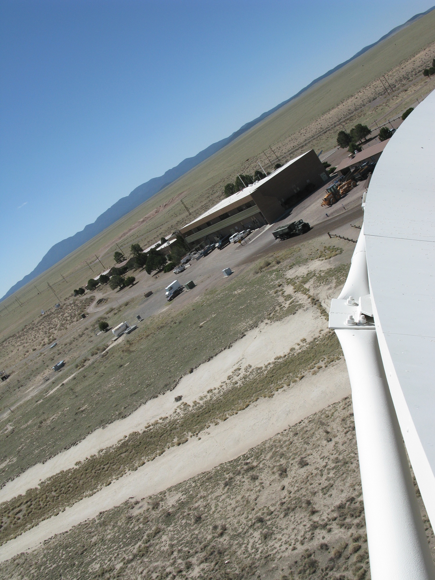
Looking over the edge
The view over the side of the dish can be a little frightening. Remember that it is safer to just hold a camera over the edge.
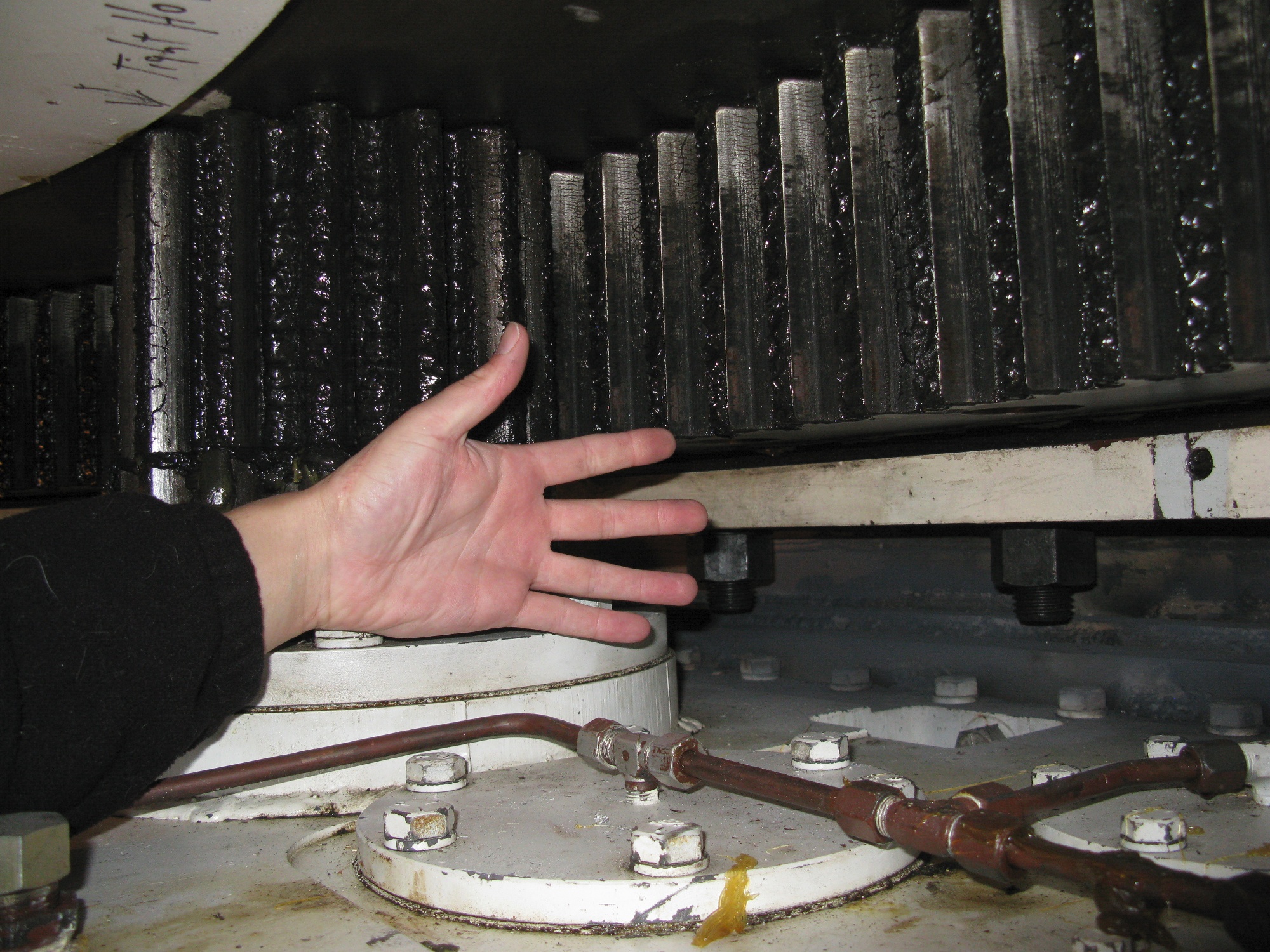
Azimuth Gear
The VLA antennas sit on a fixed base and have a bearing to allow for rotation. A large geared drive system then moves the antenna. Be sure to lock out the antenna drives prior to putting your hand near the gears.
Counterweight
Each VLA antenna has a large counterweight to balance the load on the elevation axis.
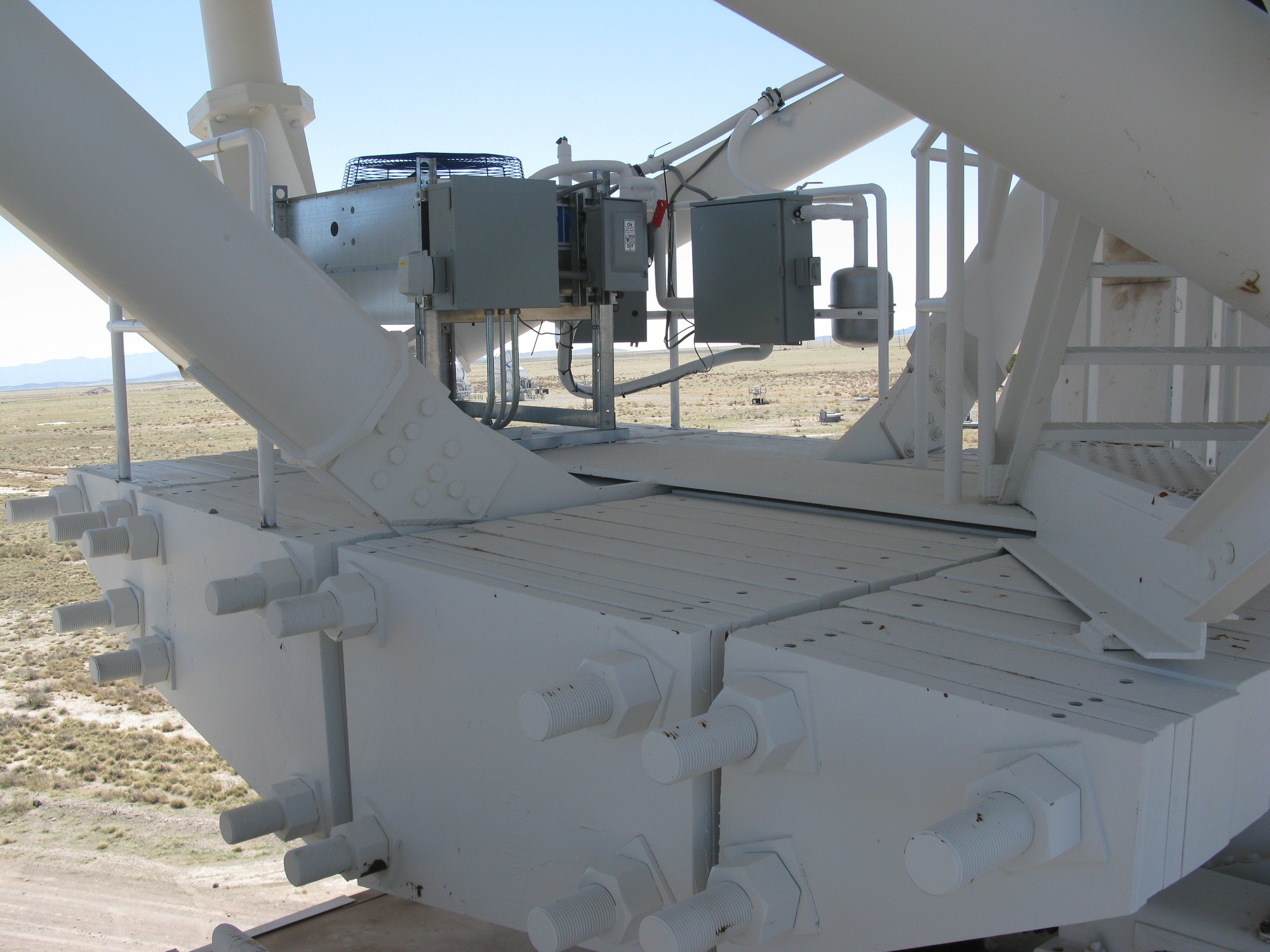
VLA FRM
The focus and rotation module (FRM) of the VLA antennas differs only slightly from that of the VLBA. They both serve the same purpose: position a subreflector to focus the beam on one of the receivers.

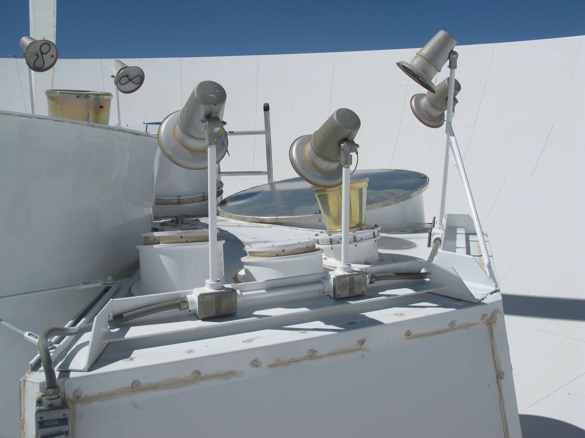
Feed horn defrosters
Being at an elevation of about 7000ft the VLA has cold winters. Frost, snow, and ice on the feed horn will interfere with the signal. So defrosters are installed to clear it off.
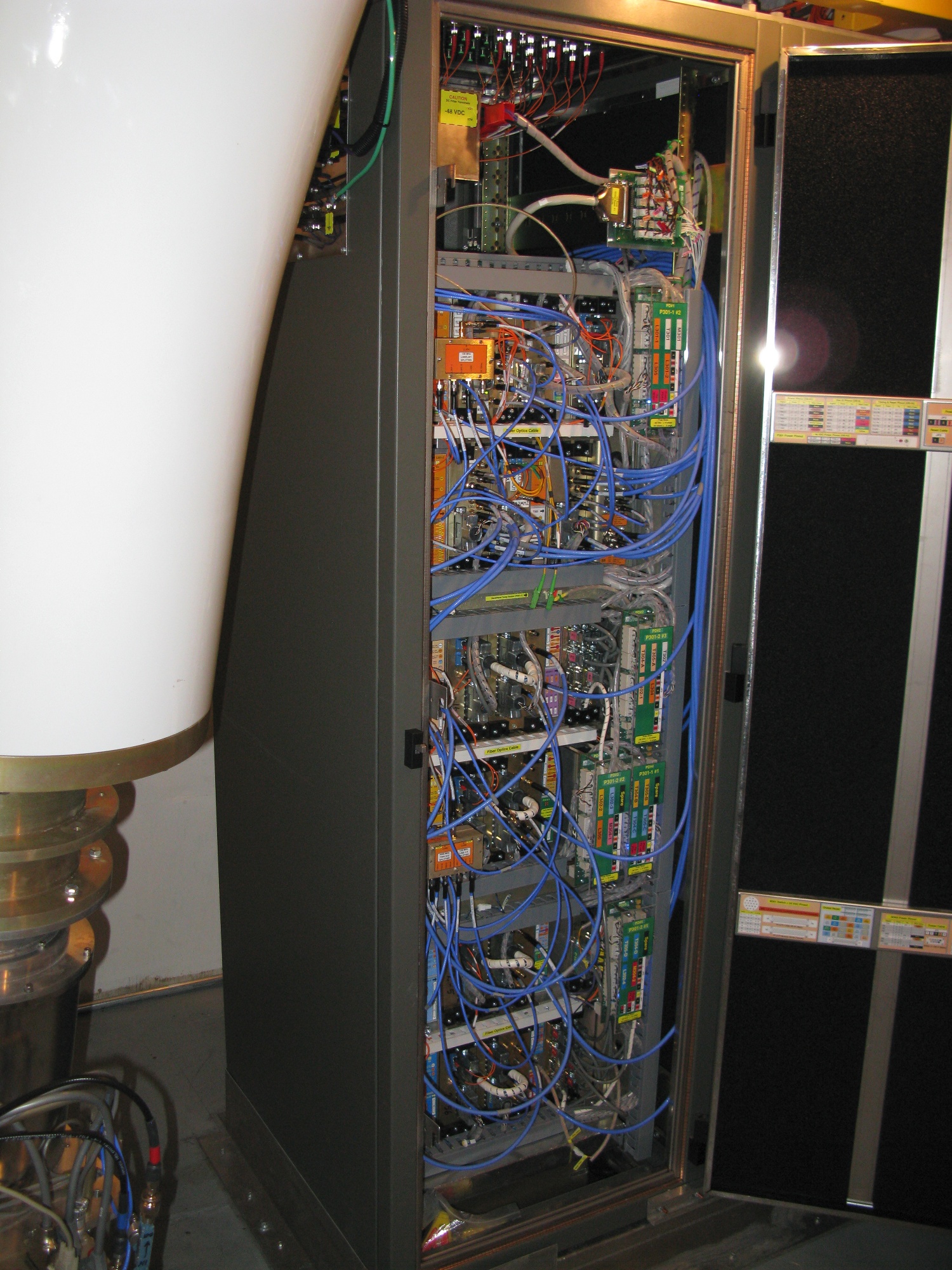
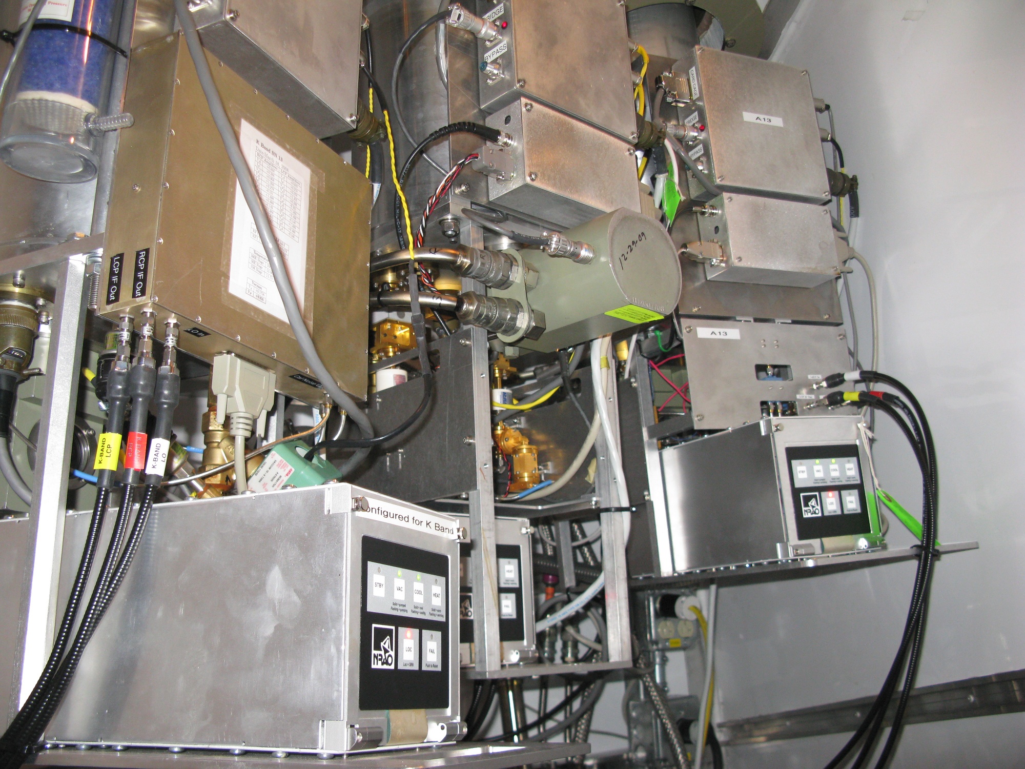
VLA Electronics Rack
Each receiver cabin has a couple racks of support electronics. Each antenna has to correctly synchronize its clock to the master clock, it has to receive and convert the RF signal, and it has to send the signal to the correlator.
In the original VLA an analog signal was sent back via waveguide. With the EVLA upgrade the signal is now digitized in the antenna and sent back over fiber optic cables.
VLA Receivers
NRAO designs and builds most of the receivers used in the antennas. Three of them can be seen here.
VLA control building
The VLA control building houses the correlator and the control room.
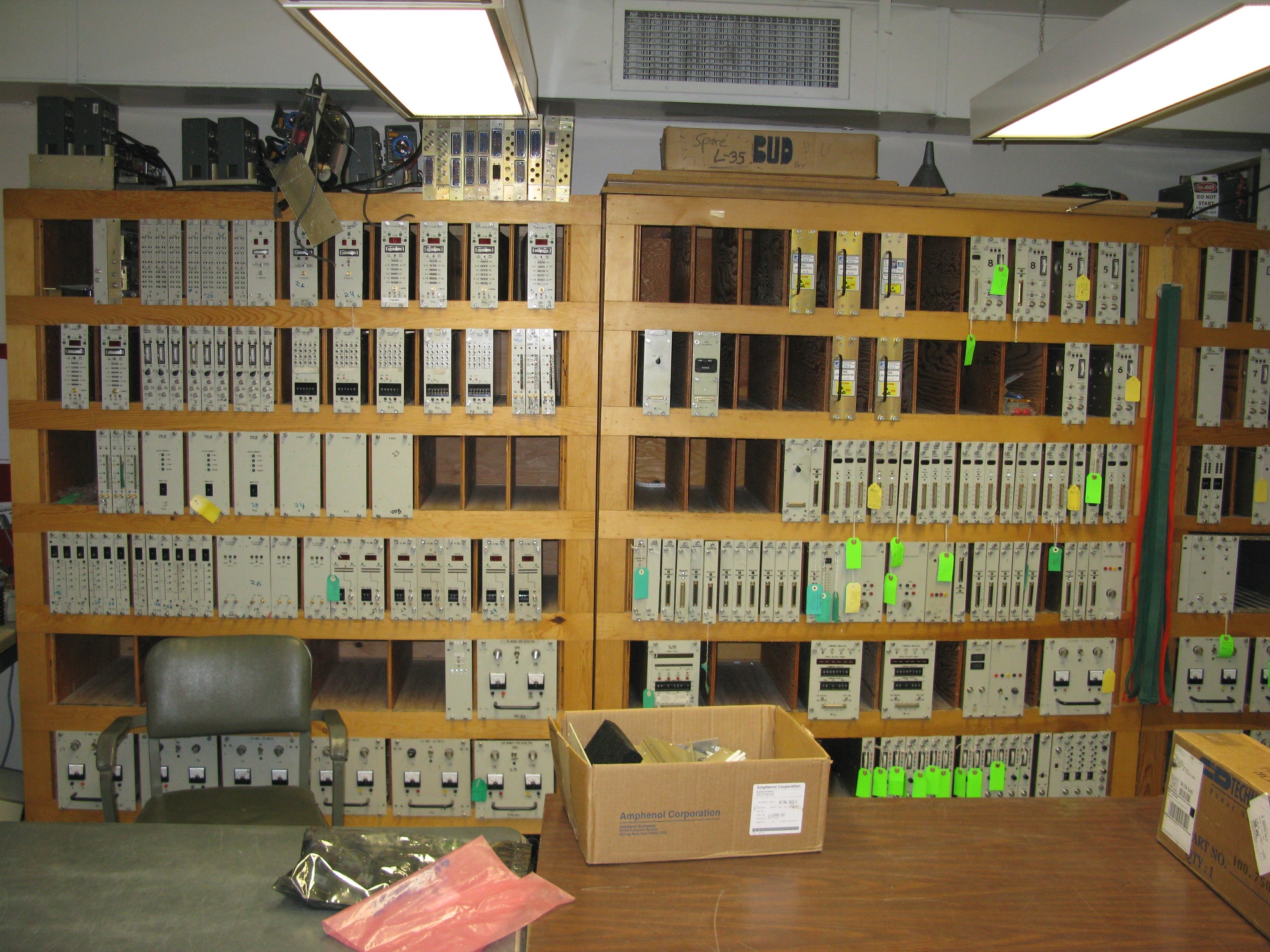
Spare Modules
Spare modules are always kept on hand, and failed modules are diagnosed and repaired. With the recent EVLA upgrade project many of the older electronics were replace with newer ones, so many of these modules are now outdated.
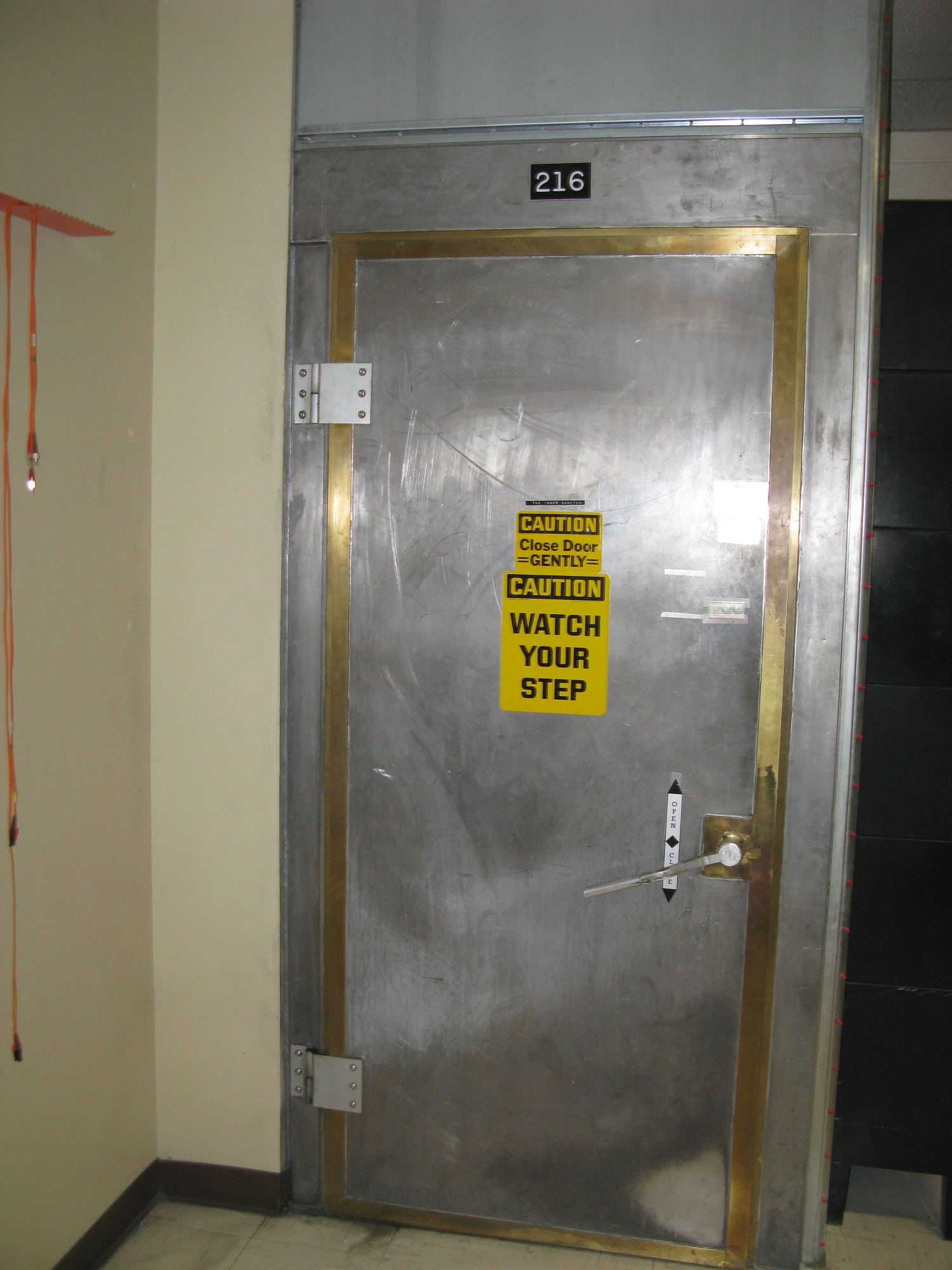
Old VLA correlator room door
Radio interference is a constant concern at the VLA. While a lot can be removed by the correlator, it is still very important to minimize interference from site electronics. Modern digital electronics generate large amounts of interference at the frequencies the VLA observes at. Shielded rooms such as this are often used to house station computers, preventing interference.
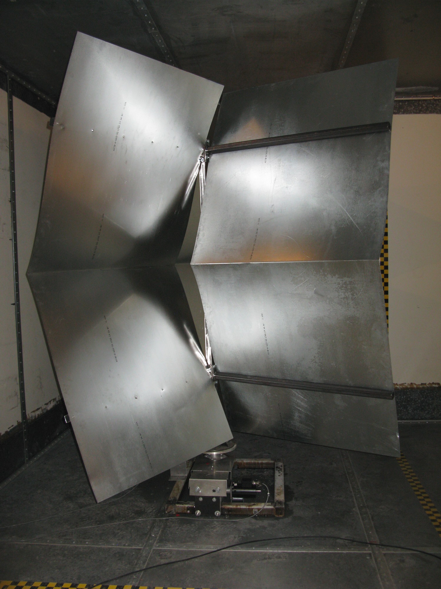
VLA RF test chamber
The VLA has an electromagnetic reverberation chamber for determining what interference a device emits. This chamber uses a combination of reflective walls, mode stirrer, and an omnidirectional antenna.
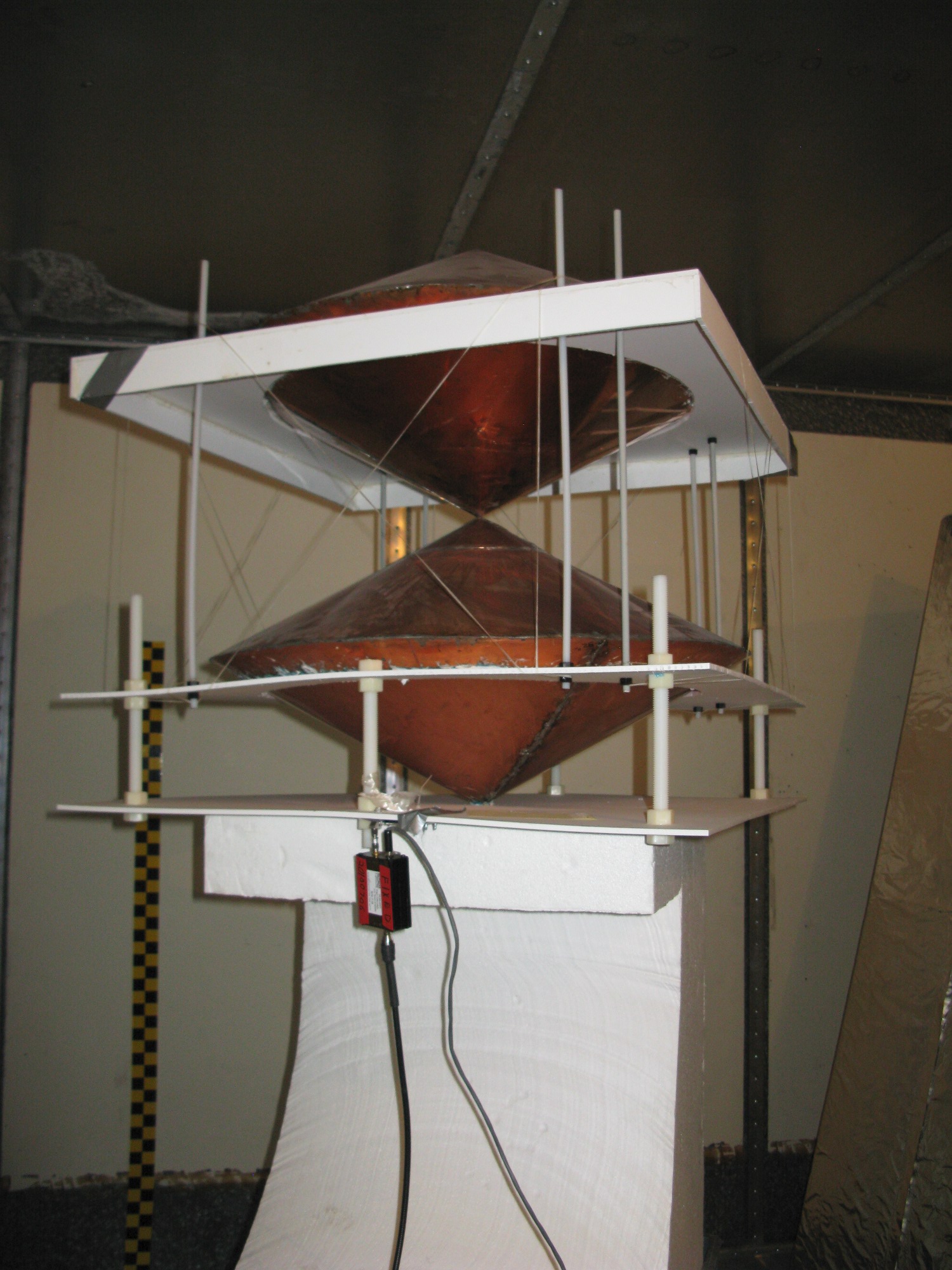
Omnidirectional antenna
This is the omnidirectional antenna used inside the test chamber.
© David C. Hunter, 2014
fb [at} dragonsdawn {dot} org
![]()
